¶ Contents
¶ 1. Machine
Protect your hands, wrists and fingers.
Do not put any of your body parts inside the machine or anywhere near the head during operation.

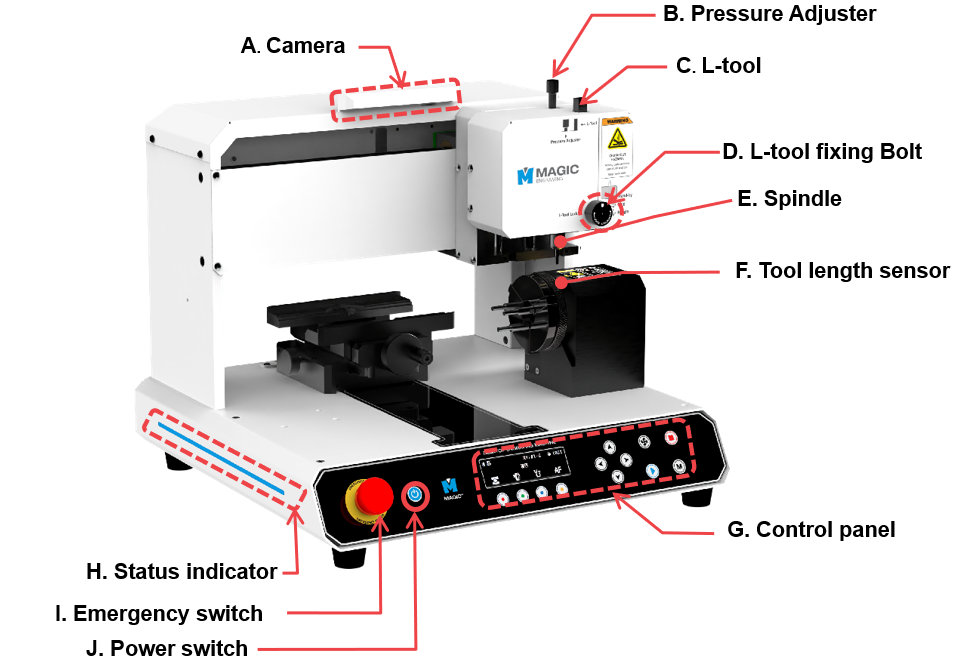
| A | Camera | Shows actual view of material to design. |
| B | Pressure Adjuster | Adjusts the pressure of the engraving tool. |
| C | L-Tool | Secures the L-tool tip when engraving on the inside of rings or bangles.
※To change tools, use a 1.5mm L-wrench. |
| D | L-Tool Fixing Bolt | Secures the L-tool. |
| E | Spindle | Secures the tool for engraving. ※To change tools, use a 2mm T-wrench. |
| F | Tool length sensor | Automatic tool length measurement sensor. |
| G | Control Panel | Controls the power button and the manual control for regulating engraving operations. |
| H | Status Indicator | Shows the status of the device via blinking interval |
| I | Emergency Switch | Stops the machine during emergency. |
| J | Power Switch | Switches the power on/off. |
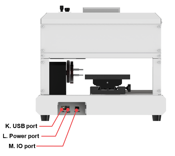
| K | USB Port | To connect USB cable to PC. |
| L | Power Port | To connect power adapter to supply power to the machine. ※Use a grounded outlet only. Do not plug the machine into an ungrounded outlet. |
| M | IO Port | To connect the dust connector. |
¶ 2. Clamp
¶ 1) Multipurpose Clamp
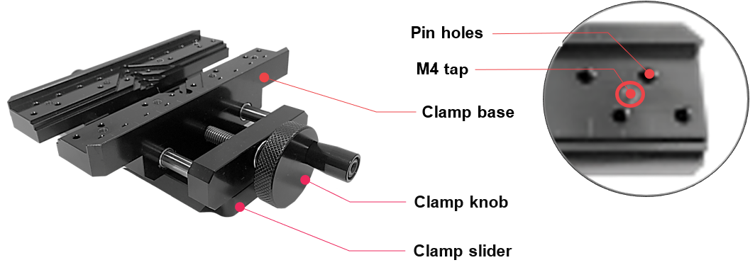
The package includes a multifunctional clamp that is easily assembled, disassembled and transformed into 3 different types of clamps. It can be adjusted according to the height of the material, and can be expanded according to the material’s thickness, size, and shape. This single clamp alone makes engraving on various materials possible without the use of any additional clamps.
¶ How to secure the material in place
Use the clamping knob to secure your material in place. To loosen or widen the clamp, turn the clamping knob counterclockwise; to fasten it, turn the knob clockwise.
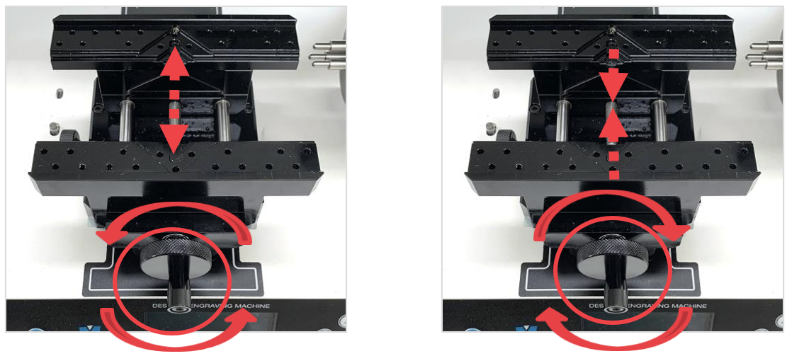
Marks may be left on the material if fastened tightly.
¶ How to position the material
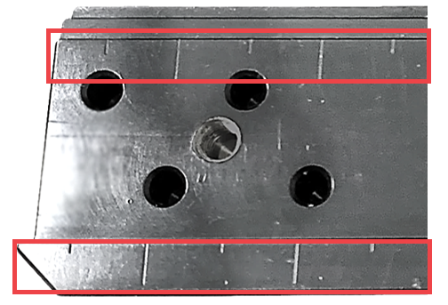
Use the vertical ruler bar as an alignment guide to help you position and align your material to the clamp with ease and accuracy. Properly place your material on the clamp then check the alignment.
¶ How to secure the material with irregular shape in place
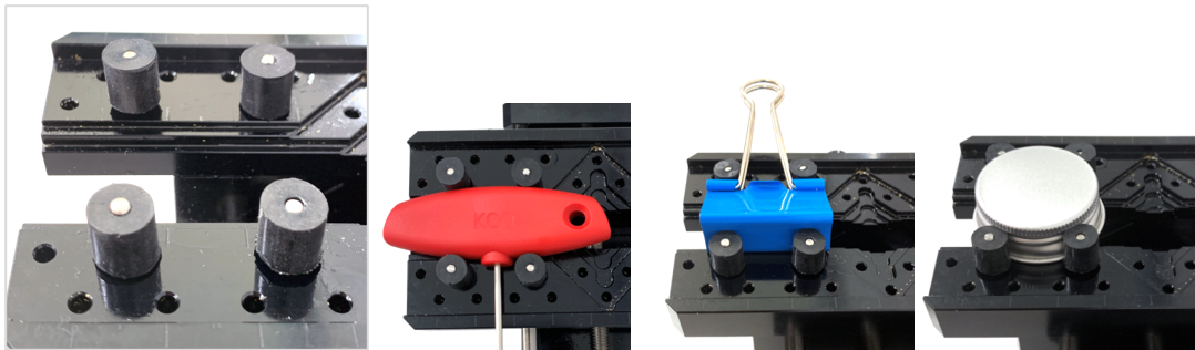
Use the clamping pins to firmly hold materials with irregular shapes in place. To secure the clamping pins to the clamp, simply insert the pins into the pin holes then fasten them.
¶ How to adjust the height of the clamp
Below are instructions on how to adjust the height of the clamp according to the thickness of the material.
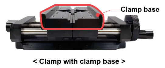
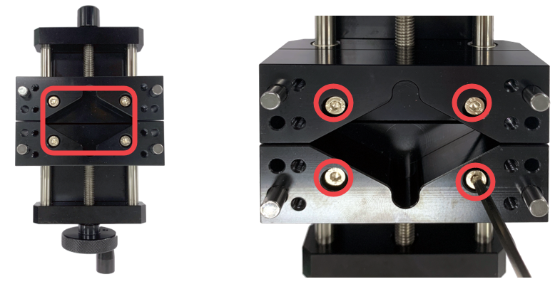
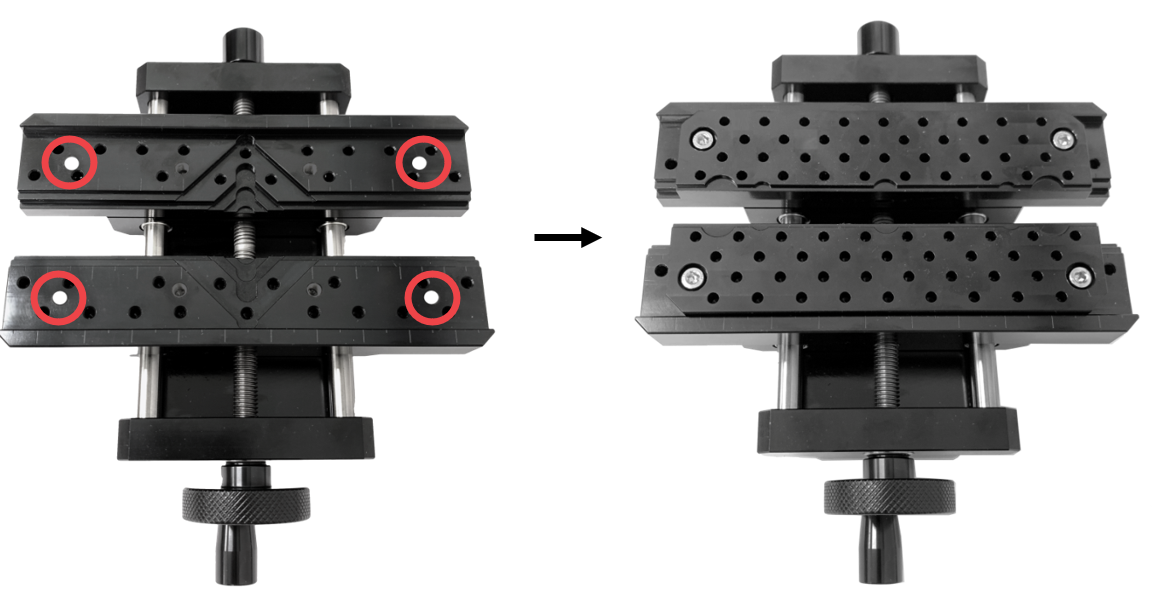
- Turn the clamp over (to the back) then screw the bolts (M4x20mm). ※Use a 3mm L-wrench to screw the bolts.
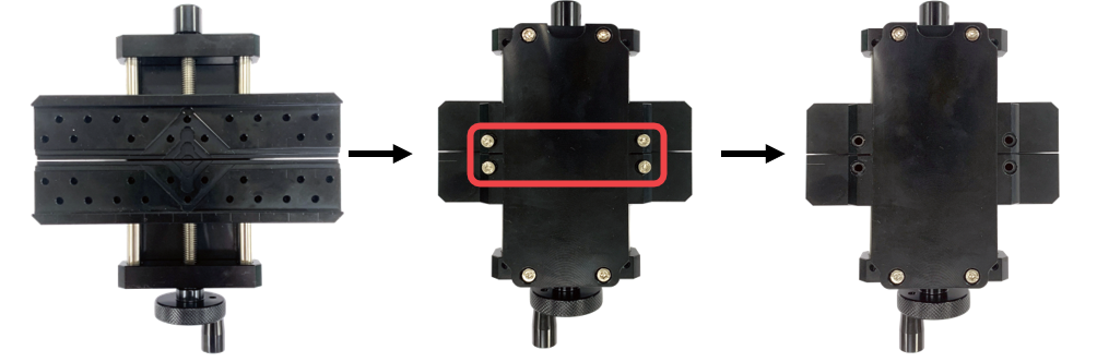
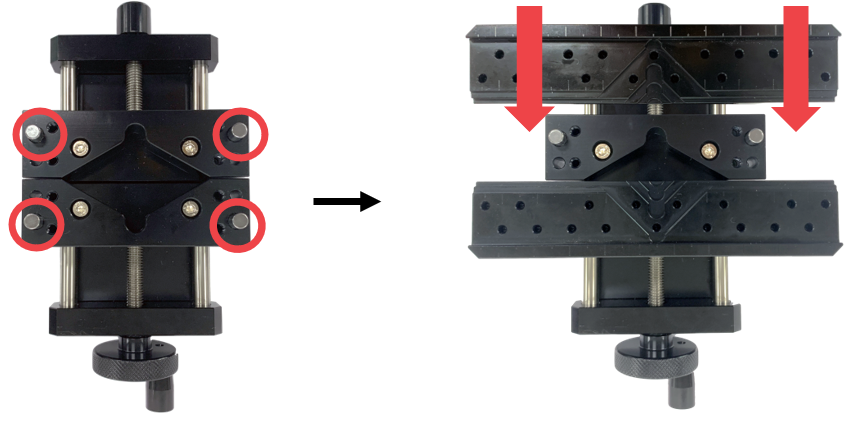
- Turn the clamp over (to the front) then pull out the clamp base.
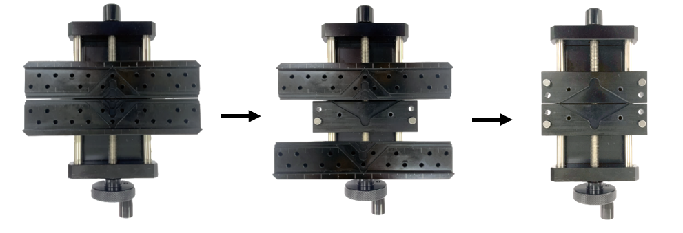
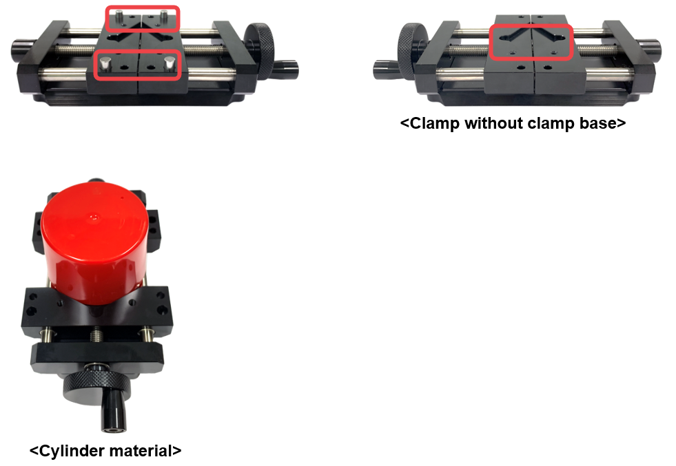
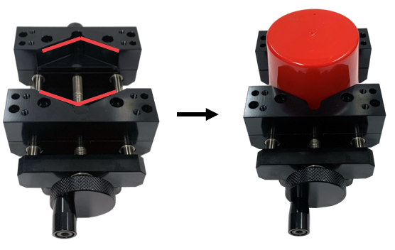
- Remove the clamping pins then secure the material to the V groove of clamp without clamp base. (See picture below for reference).
¶ Height Adjustable Clamp
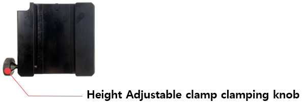
Height adjustable clamp is used to adjust the height of your material.
| Height adjustable clamp (CP-252) |
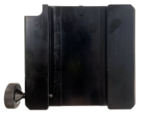 |
1EA | To adjust the height of the clamp. |
- Turn the Height Adjustable clamp clamping knob counterclockwise to detach the Multipurpose Clamp.
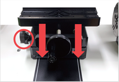
- Turn the clamping knob counterclockwise to detach the height adjustable clamp.
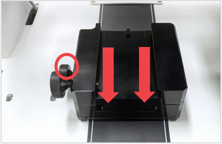
- Attach the multipurpose clamp then fasten it by turning the clamping knob clockwise.
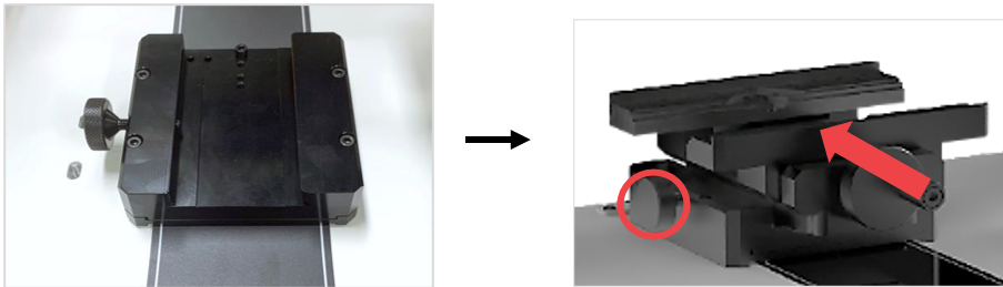
¶ How to adjust the height of the clamp
※Optional device; sold separately
Below are instructions on how to adjust the height of the clamp according to the thickness of the material.
| Spacer block (CP-250S) |
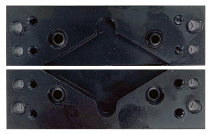 |
1EA | To adjust the height of the clamp. |
- Turn the clamping knob counterclockwise to detach the clamp.
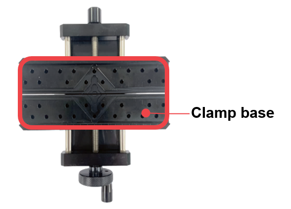
- Turn the clamp over (to the back) then screw the bolts (M4x20mm). ※Use a 3mm L-wrench to screw the bolts.
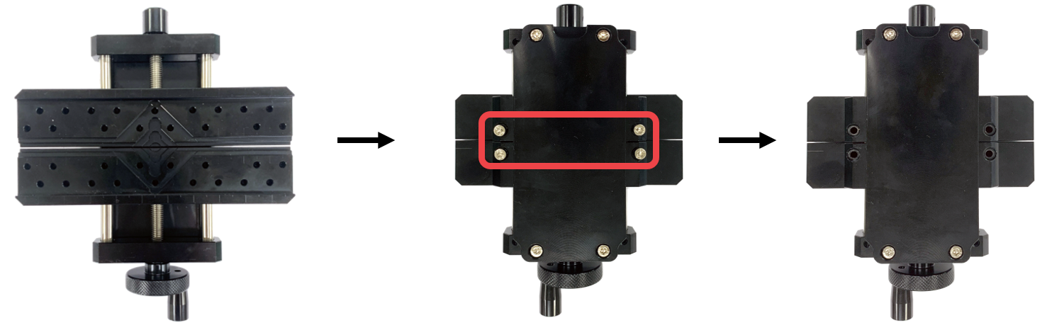
- Once the bolts are removed, turn the clamp over (to the front) then pull out the clamp base. Then, reassemble the spacer block to pin.
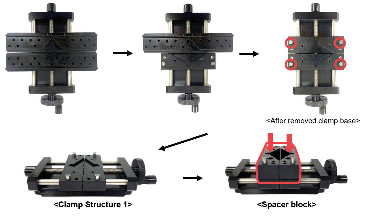
※ After secure the spacer block, then secure the material to the V groove of clamp.
- Screw the spacer block fixing bolt (M4x20mm). ※Use a 3mm L-wrench to unscrew the bolts.
- Secure the base clamp by attaching it to the pins.
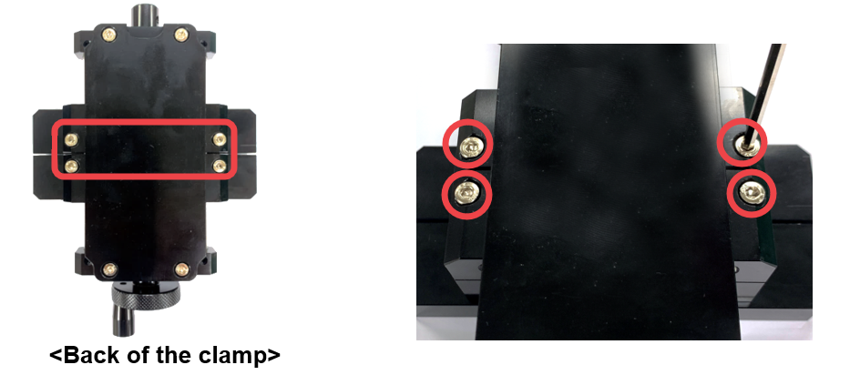
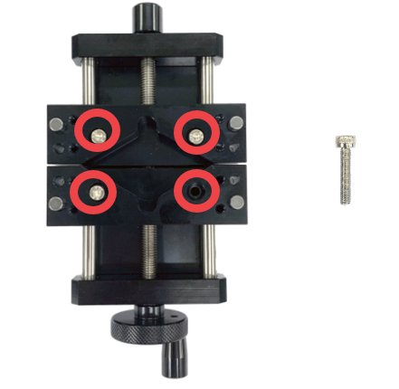
- Turn the clamp over (to the back) then unscrew the bolts (M4x40mm).
※Use a 3mm L-wrench to unscrew the bolts.
※ To assemble or reassemble the spacer block, use the appropriate bolts. Be sure to use and secure the spacer block using the correct type of bolts.
 |
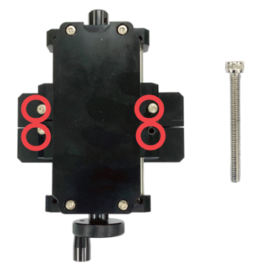 |
| Spacer block fixing bolt- M4x20mm | Clamp base fixing bolt- M4x40mm |
¶ Optional items for Multipurpose Clamp
¶ 1. Pin clamp
※Optional device; sold separately
| Pin clamp (CP-80) |
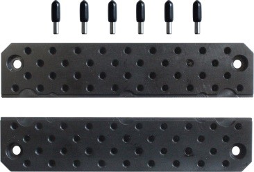 |
1SET | To hold materials with different shapes in place. |
| Pin (CP-172) |
 |
5EA | To hold materials with irregular shapes in place. |
| Wrench bolt (M4x6) |
 |
5EA | To fasten the clamp. |
| L-wrench(3mm) (CP-L30) |
 |
1EA | For tightening/unscrewing the bolt. |
¶ 2. Cutlery clamp
※Optional device; sold separately
| Cutlery clamp (CP-83) |
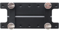 |
1SET | To firmly hold spoons in place. |
¶ 3. Watch adapter
※Optional device; sold separately
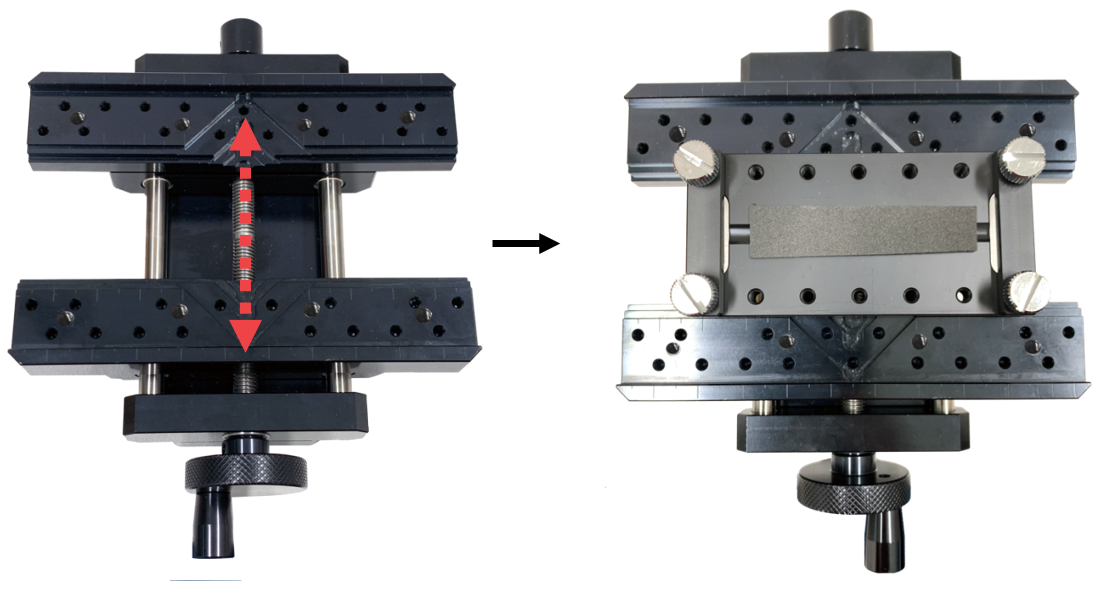
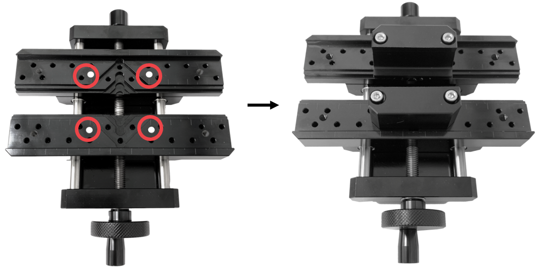
| Watch adapter (CP-84) |
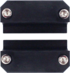 |
1SET | To firmly hold watch in place. |
| Wrench bolt |  |
5EA | To fasten the adapter. |
| L-wrench(3mm) (CP-L30) |
|
1EA | For tightening/unscrewing the bolt. |
¶ 4. Bracelet adapter
※Optional device; sold separately
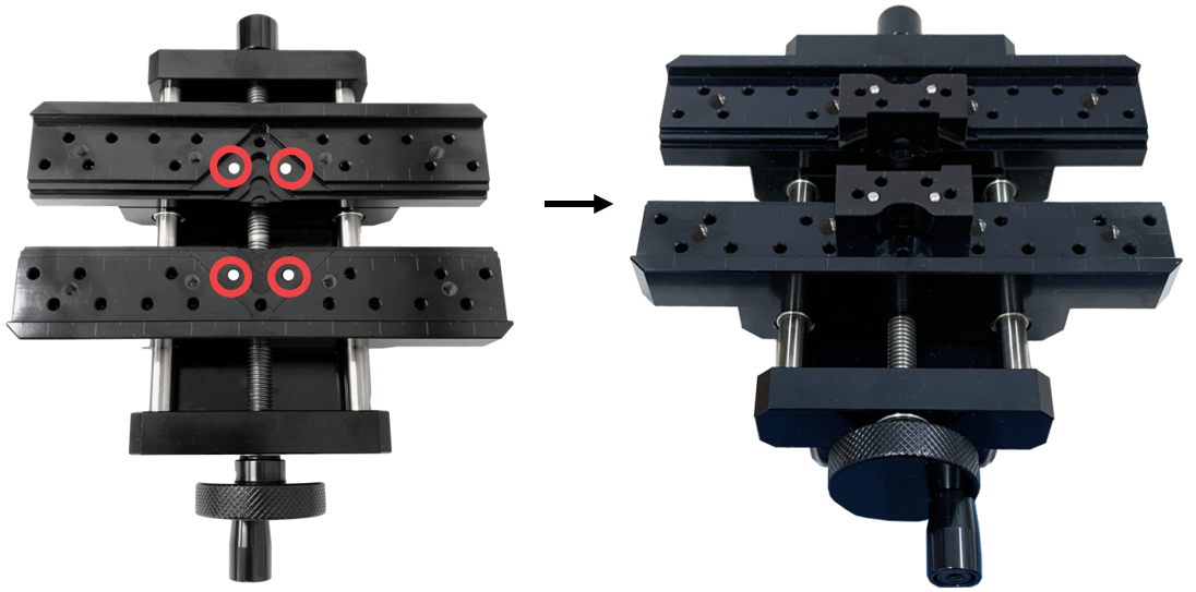
| Bracelet adapter (CP-85) |
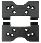 |
1SET | To firmly hold bracelets in place. |
| Pin | 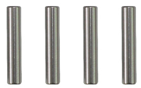 |
4EA | To secure the adapter. |
¶ 5. Bar necklace adapter
※Optional device; sold separately
| Bar necklace adapter (CP-166) |
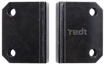 |
1SET | Jig for holding materials with narrow width (about 2-3mm) in place. (Used for securing pendants, bar necklaces, etc.) |
| Pin | |
4EA | To secure the adapter. |
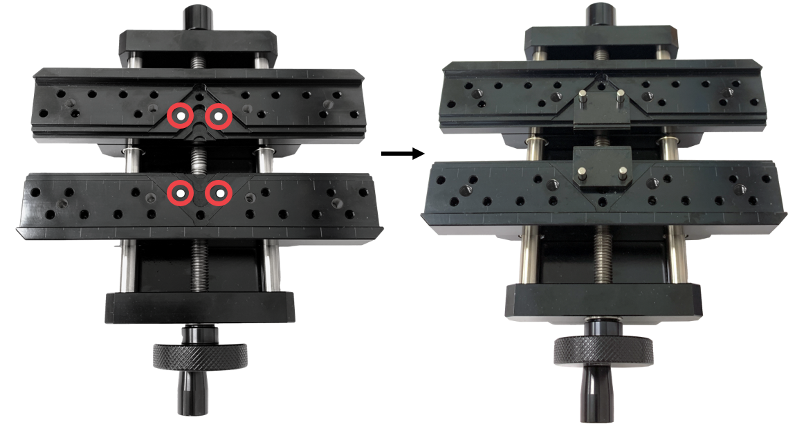
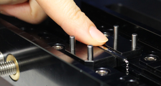
*Materials like bar necklaces or pendants may come off easily when attaching to the jig.
Press the material with your finger to secure it to the jig and be sure to not let your finger get caught while pressing.
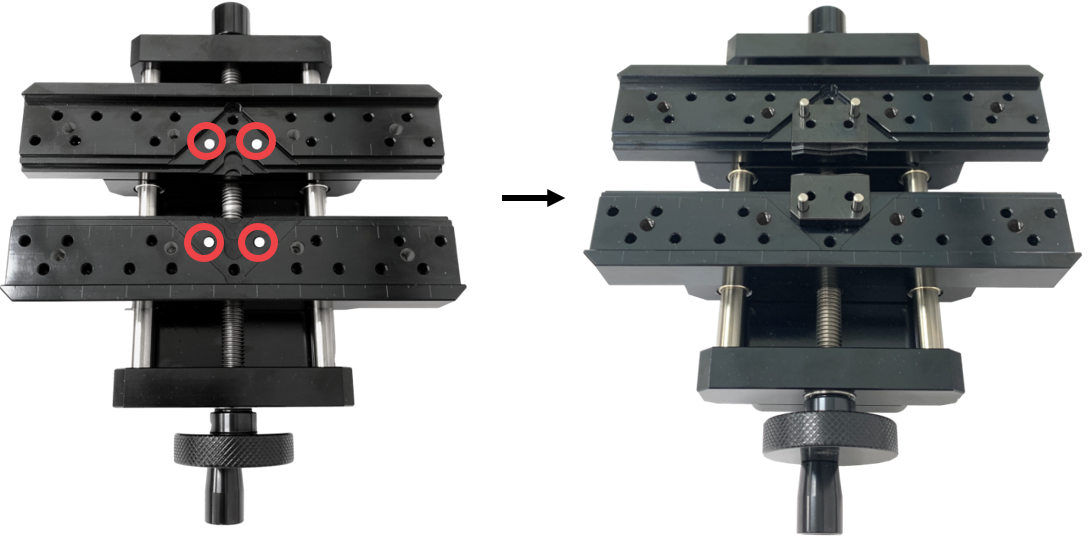
¶ 6. Curved tag adapter
※Optional device; sold separately
| Curved tag adapter (CP-182) |
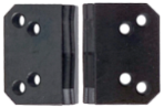 |
1SET | Jig for holding curved materials in place. (Used for securing curved pendants, chain bracelets, etc.) |
| Pin | |
4EA | To secure the adapter. |
¶ 2) Rotary Clamp
※Basic Installation
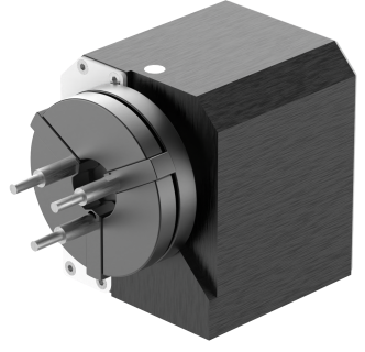
MAGIC™-E7’s package includes a rotary clamp that is used for engraving the inside and outside of a ring.
¶ How to activate ring engraving mode
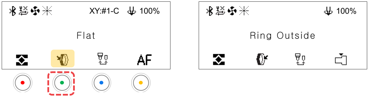
Press the rotary clamp button to activate ring inside/outside engraving mode.
¶ How to secure the ring in place
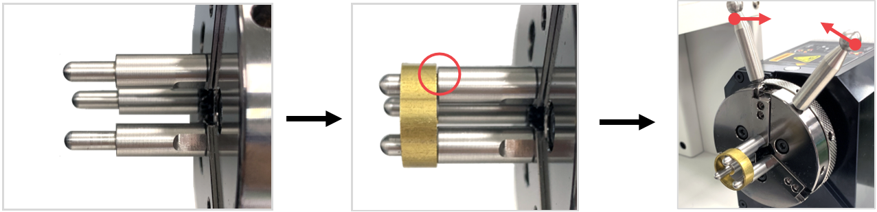
When engraving the outside
Place the ring onto the finger chucks. Rotate the rotary clamp to outward-inward directions to lock and secure the ring in place. Make sure that the ring is firmly attached and locked so it won’t fall off or spin during operation.
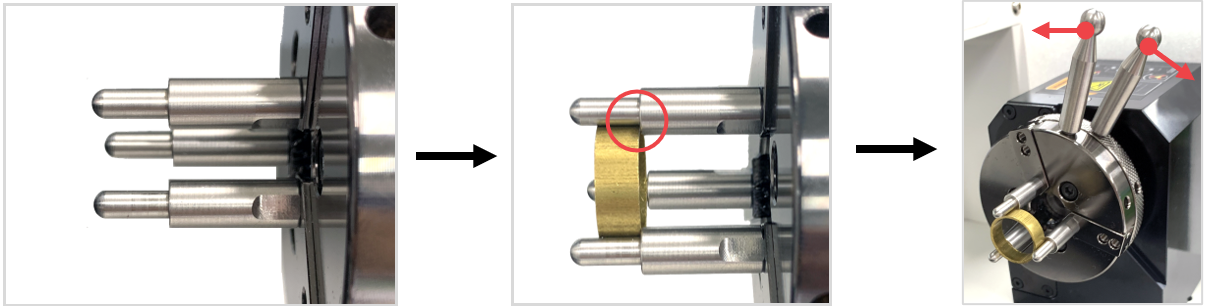
When engraving the inside
Insert the ring in between the finger chucks. Rotate the rotary clamp to inward-outward directions to lock and secure the ring in place. Make sure that the ring is firmly attached and locked so it won’t fall off or spin during operation.
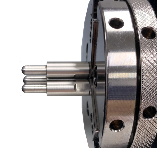
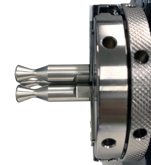
¶ Finger Chuck Types
There are three types of finger chucks available to match the shape and size of the ring.
 |
 |
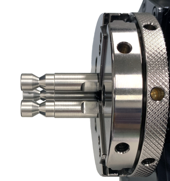 |
| Flat chuck finger ※Included in the package |
Round chuck finger (wide) ※Included in the package |
Round chuck finger (narrow) ※Sold separately |
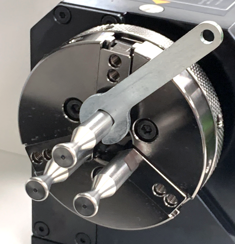
¶ How to replace finger chucks
Choose the appropriate finger chucks for your ring. Insert the finger chucks into the holes then fasten them tightly with the use of a finger chuck spanner. ※The finger chuck spanner is included in the package.
¶ 3) Tailstock
※Optional device; sold separately
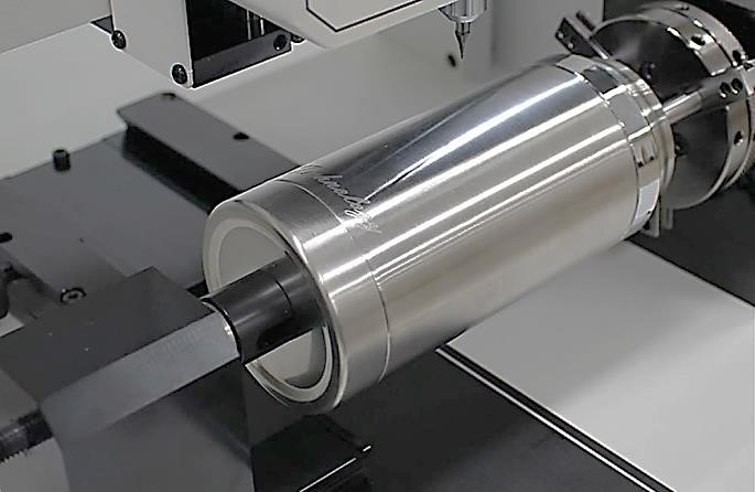
Tailstock is used to firmly hold cylindrical materials in place. It is specifically used to avoid objects with cylindrical shapes such as pen, tumbler and wine glasses to tilt to one side during engraving process.
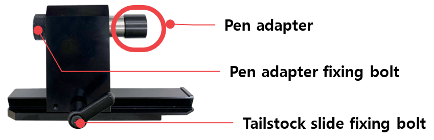
-Height (from bottom to central axis): 69mm
-Lateral distance (from left to right): 109.5mm
To set up the tailstock the following tools are needed:
| Tailstock (CP-251) |
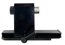 |
1EA | To hold pens in place. |
| Pen adapter (CP-251P) |
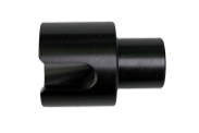 |
1EA | To hold pens in place; it goes with a tailstock. |
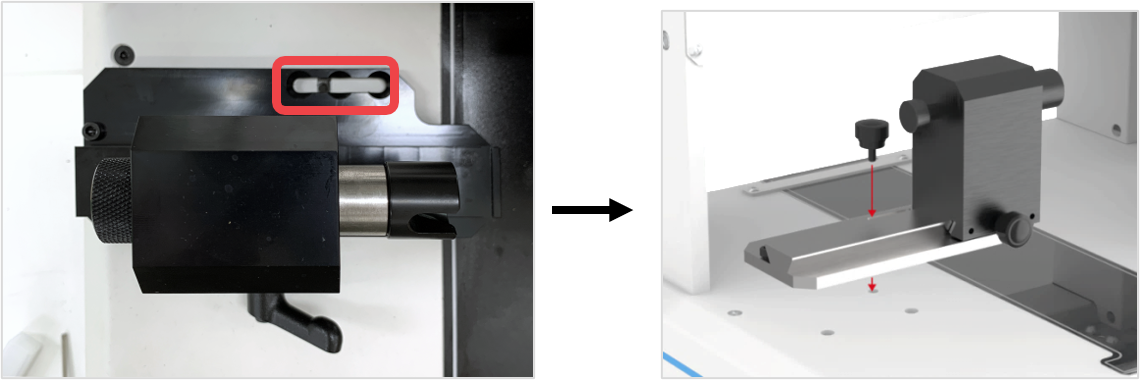
| Tailstock fixing bolt (CP-251B) |
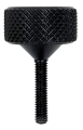 |
1EA | For fastening the tailstock. |
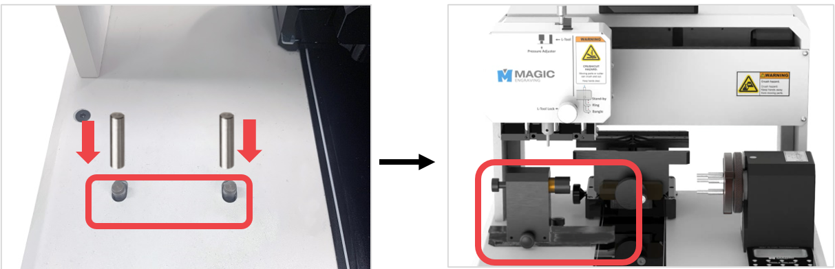
| Pin (6Øx25mm) |
 |
2EA | To secure the tailstock. |
¶ How to set up the tailstock
- Insert the pin into the pin holes.
2. Secure the tailstock with a tailstock fixing bolt.
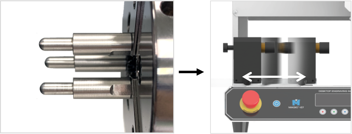
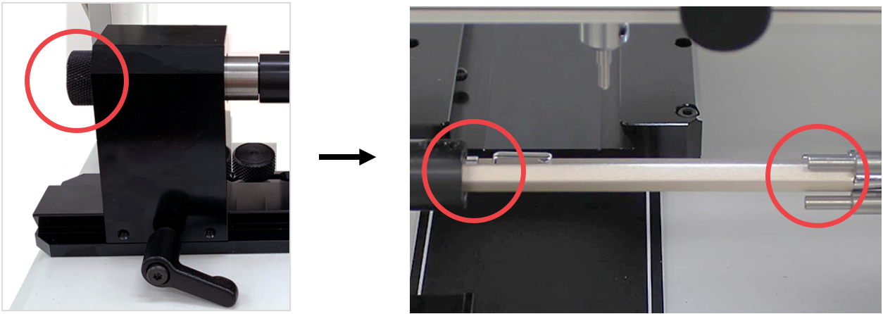
- Use the finger chucks of the rotary clamp to clamp your material. Once your material is clamped, push the tailstock to the right side until it touches the tip of your material. ※The device can slide left to right/right to left.
- Fasten the tailstock slide fixing bolt to secure your material.
¶ 3. Keypad
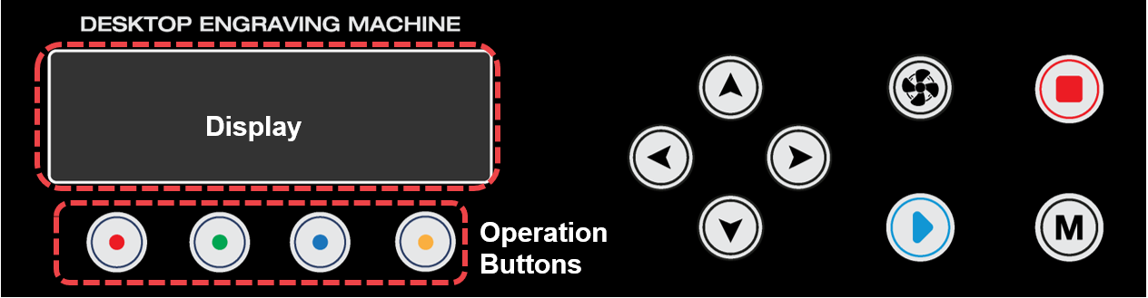
| Display | Status display | ||
| Operation Buttons | Activate the operations intended to perform | ||
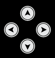 |
Direction Key (X,Y/Z/A) |
Engraving area adjustment  (X) Moves X axis (X) Moves X axis  (Y)(Z)(A) Moves Y/Z/A axis (Y)(Z)(A) Moves Y/Z/A axis ※Axis movement can be changed by using the operation buttons. |
|
 |
Vacuum ON/OFF | Chip collector power button • Automatic control: The device starts automatically once the engraving operation begins and stops automatically once the engraving operation is completed. • Manual operation: Automatic control is deactivated if the device is manually switched on. Once the engraving operation is completed, the device should be manually turned off. ※ We strictly advise our users to use the Chip collector during engraving operation for safety. The Chip collector prevents exposure form harmful inhalable particles and debris like metal chips and dusts which may cause eye injury if they get stuck in the eye or respiratory problems if inhaled. |
|
 |
Start | Start marking button • Start marking: Long-press (for 2 seconds) the  button to start marking. button to start marking.• Repeat marking: Press the button to finish marking, then double-press (tap twice) the button to repeat marking.• Menu: Press OK when using the menu. |
|
 |
Menu | Enter the menu mode | |
 |
Stop | Stops/cancels marking | |
¶ 4. Menu
To enter Menu mode, press button. Select a menu item using the and buttons then press button to enter the menu item.
| 1. Tool Change | Changes the tool. | |
| 2. Select Origin | Sets the current position to the clamp origin. | |
| 3. Calibration | 1. Touch Sensor | Adjusts touch sensor settings. |
| 2. Pointer/Flat | Adjusts pointer/flat settings. | |
| 3. Pointer/Rotary | Adjusts pointer/rotary settings. | |
| 4. Pointer/L-Tool | Adjusts pointer/L-Tool settings. | |
| 4. Measure Z-Ref | 1. Height Only 2. Horizontal(X) Slope 3. Vertical(Y) Slope 4. Plane(XY) Slope *In rotary mode, only [1. Height Only] is enabled. |
|
| 5. Ring Inside Area Check | Sets a method for checking the inner diameter engraving area: 1. L-tool 2. Laser pointer |
|
| 6. Chuck Revolution | Rotates the rotary chuck. | |
| 7. Adjust Brightness | 1. Status LED | Adjusts status LED brightness |
| 2. Inside LED | Adjusts inside LED brightness | |
| 3. Pointer | Adjusts focus laser pointer brightness | |
| 8. Vacuum Setup | Sets the Chip collector function. -Set to automatic control. -Set the Chip collector type: Dry/wet type |
|
| 9. Tool-Pos Recording | Records your current location; set whether to activate or not. | |
| 10. Auto Zref on Repeat | Sets Auto Zref method for repetitive engraving: 1. No measurement 2. Height measurement 3. Height measurement + area check |
|
| 11. Front cover | Selects whether to use the front cover or not. ※Optional device; sold separately |
|
¶ 5. Display
The display shows the status, functions, mode, and check messages. Icons are displayed differently depending on the selected function. The four buttons at the bottom represent different functions and each function vary depending on the selected mode.
¶ 1) Standby-Flat
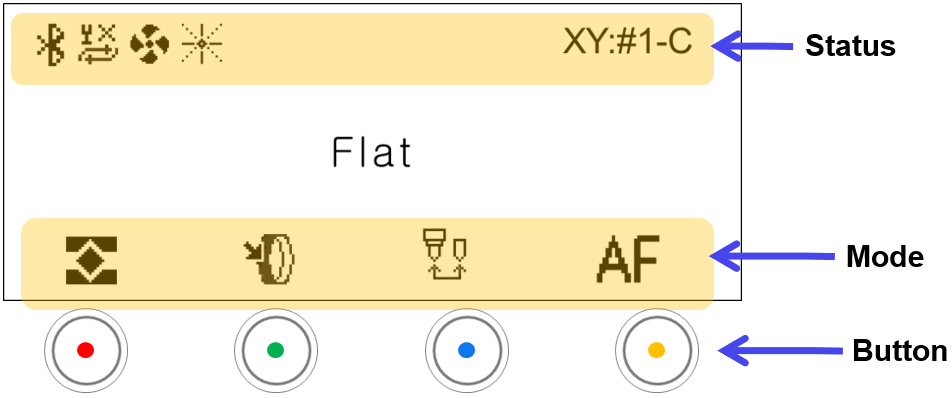
| Status | ||
|---|---|---|
 |
Bluetooth | Icon appears when Bluetooth is activated |
 |
Auto Zref on Repeat |  : No measurement : No measurement : Height measurement only : Height measurement only : Height measurement + area check : Height measurement + area check |
 |
Chip collector Power | Chip collector ON/OFF: Icon does not appear when OFF |
 |
Focus Pointer | Laser pointer ON/OFF |
 |
Front Cover | Selects whether to use the front cover or not. ※Optional device; sold separately |
| XY:#1-C | X-Y Origin | X-Y origin •[#1]: Clamp No. (1-5) •[C]: Origin No. (C: Center; origin No.: 1-8) |
| Mode | ||
|---|---|---|
 |
Flat Mode | Switches to flat mode |
 |
Rotary Mode | Switches to Rotary mode • The mode changes in sequence (OUTER DIAMETER → INNER DIAMETER → OUTER DIAMETER) in a loop whenever the button is clicked. • Switched to the INNER DIAMETER mode instantly if double-clicked |
 |
Tool change | Switches to tool change mode |
 |
Auto focus | Activates camera auto focus position • Auto moves to view position after height measurement • Refreshes the camera display at MagicEngrave. ※Variety of features available for use once MagicEngrave software is enabled. |
¶ 2) Standby–Rotary
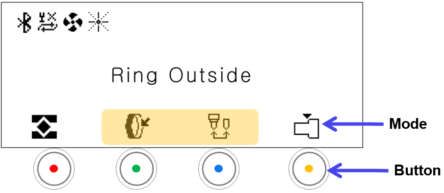
| Mode | ||
|---|---|---|
 |
Rotary Mode | Switches to rotary mode : Changes to rotary inner diameter mode : Changes to rotary outer diameter mode |
|
Finger Mode | The mode changes in sequence (Flat finger → Round finger → cylinder) in a loop whenever the button is clicked. Flat Finger Flat Finger Round Finger Round Finger Cylinder (Used for cylinder engraving / ring cutting) Cylinder (Used for cylinder engraving / ring cutting) |
¶ 3) Move Mode-Flat
Press one of the buttons in the [STANDBY] mode to activate [MOVE].
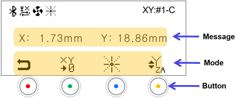
| Message | |
|---|---|
| X-Y Position | The message on display varies depending on the Y-axis mode: •Y→Y: X-Y axis position •Y→Z: Z-axis position •Y→A: A-axis position |
| Mode | ||
|---|---|---|
 |
Standby Mode | • Switches to the STANDBY mode • Switches automatically to [STANDBY] mode if not in use for 10 seconds. Press any buttons to activate [MOVE] mode. |
 |
Save Origin | Saves the current position as the XY origin *Short-press: Temporary save *Long-press: Permanent save  Y-axis movement mode: Save XY Origin Y-axis movement mode: Save XY Origin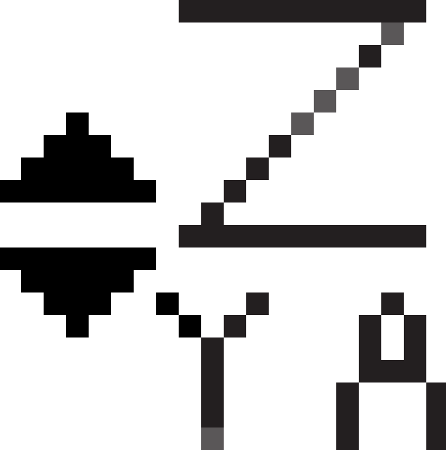 Z-axis movement mode: Z-axis movement mode:  Save Z Origin Save Z Origin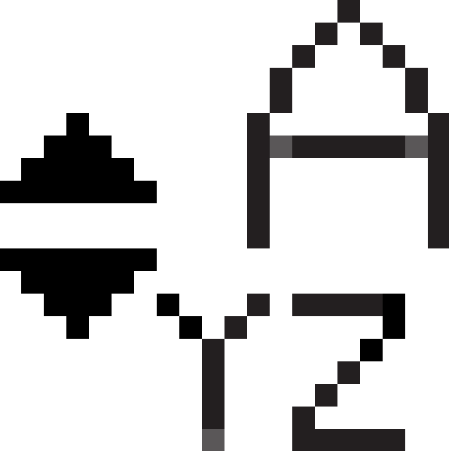 A-axis movement mode: A-axis movement mode:  Save A Origin Save A Origin |
|
Laser Pointer | Turns ON/OFF the laser pointer |
|
UP-DOWN Button Settings | The mode changes in sequence (Y-axis → Z-axis → A-axis → Y-axis) in a loop whenever the button is clicked.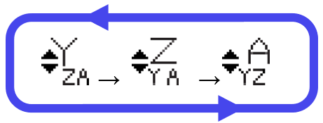 |
¶ 4) Move Mode-Rotary
Press one of the buttons in the [STANDBY] mode to activate [MOVE].
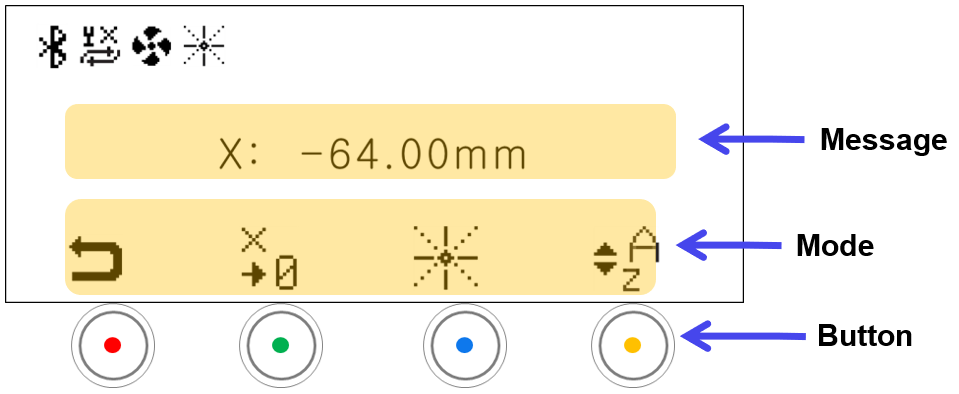
| Message | |
|---|---|
| A-axis Position | Displays the A-axis position |
| Mode | ||
|---|---|---|
|
Standby Mode | • Switches to the STANDBY mode • Switches automatically to [STANDBY] mode if not in use for 10 seconds. Press any buttons to activate [MOVE] mode. |
 |
Save Origin | Saves the current position as the XY origin *Short-press: Temporary save *Long-press: Permanent save • If  (A-axis mode): If the laser pointer is ON, the laser pointer position of the current finger is saved as the origin. (A-axis mode): If the laser pointer is ON, the laser pointer position of the current finger is saved as the origin.• If 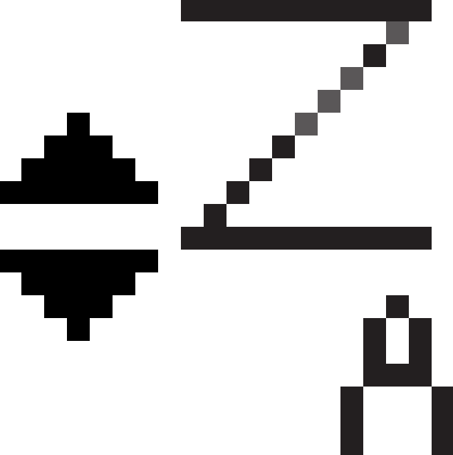 (Z-axis mode): The SAVE ORIGIN icon changes to ‘ ’, and the curent Z-axis position is saved as the origin. (Z-axis mode): The SAVE ORIGIN icon changes to ‘ ’, and the curent Z-axis position is saved as the origin.- Outer diameter mode: Z-axis origin of outer diameter - Inner diameter mode: Z-axis origin of inner diameter |
|
UP-DOWN Button Settings | The mode changes in sequence (A-axis → Z-axis) in a loop whenever the button is clicked.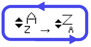 |
¶ 5) Engraving mode
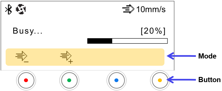
 |
Engraving Speed Control | Reduces engraving speed by 1mm/s whenever the button is pressed. |
 |
Increases engraving speed by 1mm/s whenever the button is pressed. |
¶ 6) Pause
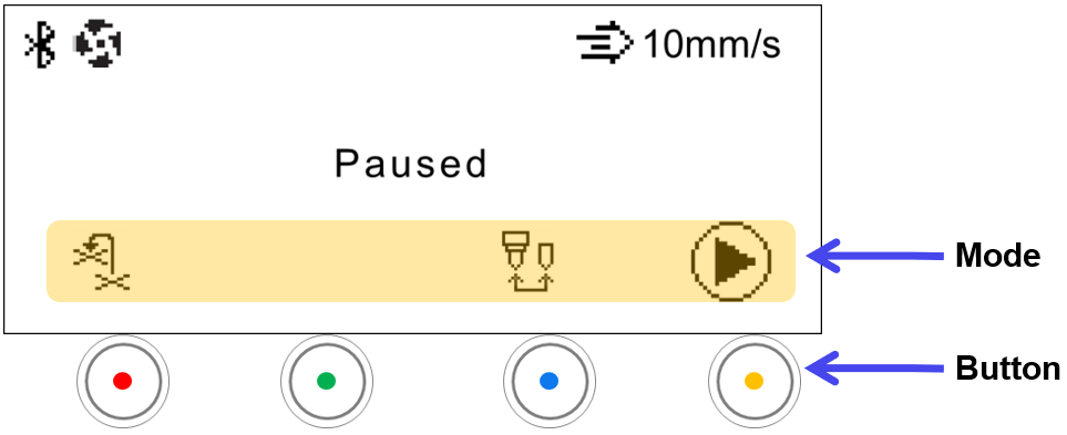
| Mode | ||
|---|---|---|
 |
Return back to Previous position | Returns back to the previous position and resumes engraving. |
|
Tool Change | Switches to tool change mode |
 |
Resume | Resumes engraving. |
¶ 6. Status Indicator
The status indicator is placed at the bottom left side and bottom right side of the machine. It is used to indicate the status of the device.
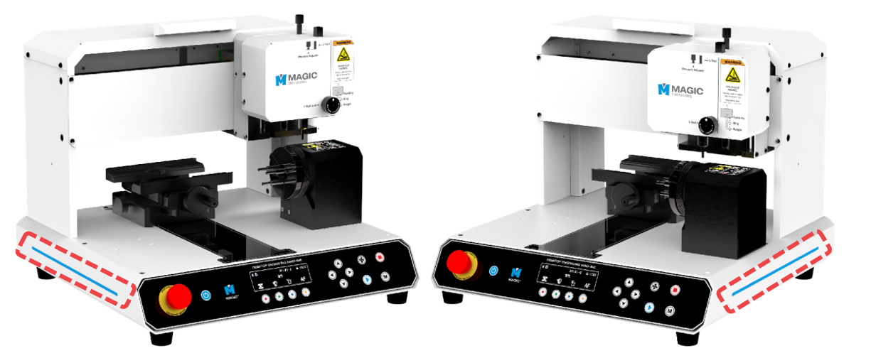
The machine displays flashing or blinking lights to show its current status. The lights displayed indicate the following status:
| Status | Blinking Interval |
| Waiting |  |
| Engraving | |
| Operating |  |
| Notification |  |
| Error |  |
Press button (for 2 seconds) to enter menu mode.
Select [7. Adjust Brightness] then press button.
| 7. Adjust Brightness | 1. Status LED | Adjusts status LED brightness |
| 2. Inside LED | Adjusts inside LED brightness | |
| 3. Pointer | Adjusts focus laser pointer brightness |
Select [1. Status LED] then press button.
Adjust the brightness using the (Direction X) buttons.

¶ 7. Switching Tools

Do not let any of your body parts or any foreign objects get caught in the machine during operation.
The tools of the machine are sharp, and may cause serious physical injury.
¶ Spindle
| Name | Picture | Quantity | Usage |
| T-wrench (2mm) |
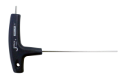 |
1EA | Tool for tightening/unscrewing of bolt. |
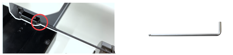
As shown below, insert the 2mm wrench into the fixing bolt. Turn the wrench to the left to unscrew bolt. To prevent the tool from falling to the floor, grab tool with your hand then pull it out. Once the tool is removed, replace it with a new tool then secure it using a wrench for tightening bolts. ※See package contents
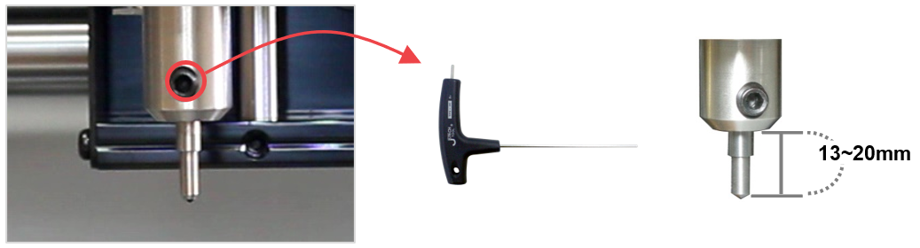
When unscrewing the tool fixing bolt, hold the tool with your hand while unscrewing to avoid the bolt from dropping on the floor.
¶ L-Tool
| Name | Picture | Quantity | Usage |
| L-wrench (1.5mm) |
 |
1EA | Tool for tightening/replacement of bolt. |
| L-tool fixing bolt (M3x4) |
 |
3EA | L-tool tip fixing bolt |
As shown below, insert the 1.5mm wrench into the fixing bolt. Turn the wrench to the left to unscrew bolt. To prevent the tool from falling to the floor, grab tool with your hand then pull it out. Once the tool is removed, replace it with a new tool then secure it using a wrench for tightening bolts. ※See package contents