¶ Contents
- 1. Touch Sensor (Tool Calibration)
- 2. Laser Pointer Calibration
- 3. Saving Multi-performance Clamp Origin Position
- 4. Saving New Clamp Origin Position
- 5. Chuck Finger Origin point
- 6. Rotary Clamp Origin point (Z axis)
- 7. Camera calibration
※ The machine is initially set up at the factory. Please contact your reseller first before making any changes to the settings of the machine.
※ Only carbide and diamond tools can be calibrated. Do not calibrate tools such as endmill and cutter.
※ Be sure to unlock the pressure lock when calibrating the machine. Nose, tool and material can be damaged if the head is fixed or when the pressure lock is locked.
¶ 1. Touch Sensor (Tool Calibration)
- Place and secure the material on the clamp.
- When attaching the tool, keep the length short as possible.
- Press
 (Flat) on operation button to move the tool to the clamp.
- Press
 button to enter menu mode.
- Use


 buttons. When 3.Calibration menu appears on the LCD window, press and hold
  button to run the menu.
- Select “1.Touch Sensor” then press and hold button to run the menu.
- The tool will be lowered and come in contact with the material and will be placed in the center of the clamp.
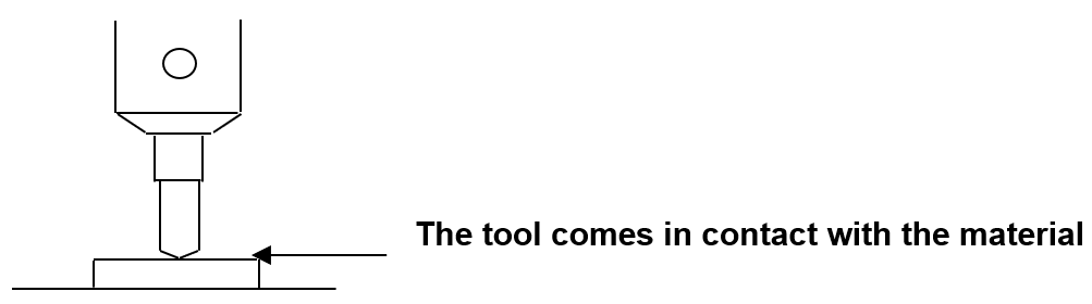
- Lower the tool by using buttons or loosening the fixing bolt of the tool with a wrench, or lift the material with your hand to make the tool and material come in contact as shown in the picture below.
- Long-press and hold button (for more than 3 seconds) until it beeps to confirm that the setting is saved then the tool will measure the material’s height.
¶ 2. Laser Pointer Calibration
¶ Spindle
- Place and secure a flat material on the clamp.
- Press button to enter menu mode.
- Use buttons. When 3.Calibration menu appears on the LCD window, press button to run the menu.
- Select the “3.Pointer/Flat” then press button to run the menu.
- The tool draws a cross (+) line on the material and the laser pointer is turned on.
- Move the laser pointer to the center of the cross by using the direction keys then press button.
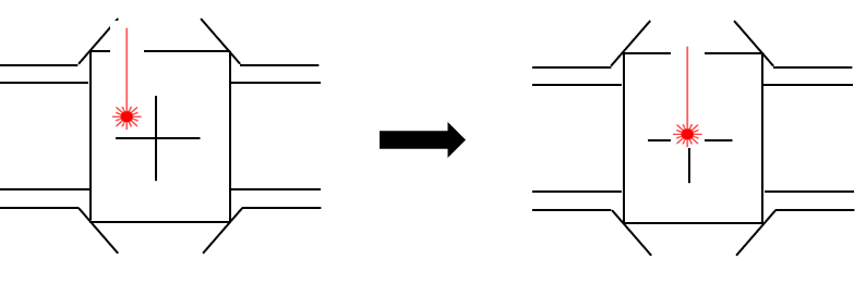
- The laser pointer moves closer to the material to calibrate the laser pointer’s origin. Move the laser pointer to the center of the cross by using the direction keys on the engraving machine then long-press and hold the button (for more than 3 seconds) until it beeps to confirm that the setting is saved.
¶ Rotation clamp
- Remove the installed clamp. To remove the installed clamp, turn the clamping knob to the left then pull out the clamp and spacer block.
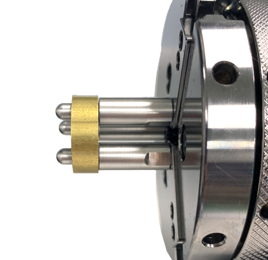
- Secure the ring to the rotation clamp.
(When setting the laser pointer origin, rings with 18mm width (Max.18mm(0.7in) can be used. Rings with width over 18mm (Over 18mm(0.7in) cannot be used.
- Press button to move the tool to the clamp.
- Use buttons. When 3.Calibration menu appears on the LCD window, then press button to run the menu.
- Select the “4.Pointer/Rotary” then press button to run the menu.
- The tool draws a cross (+) on the material and the laser pointer is turned on.
- Use the direction keys to move the laser pointer to the center of the cross then press button to save the settings.
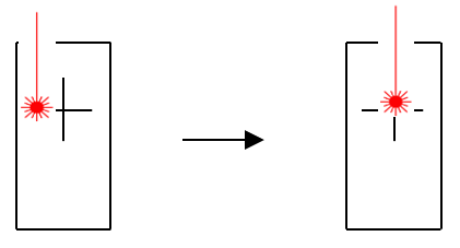
- The laser pointer moves closer to the material to calibrate the laser pointer’s origin. Move the laser pointer to the center of the cross by using the direction keys on the engraving machine then press and hold the button (for more than 3 seconds) until it beeps to confirm that the setting is saved.
¶ L-Tool
- Remove the installed clamp. To remove the installed clamp, turn the clamping knob to the left then pull out the clamp and spacer block.
- Secure the ring to the rotation clamp.
(When setting the laser pointer origin, rings with 18mm width (Max.18mm(0.7in) can be used. Rings with width over 18mm (Over 18mm(0.7in) cannot be used.
- Press button to enter menu mode.
- Press button. When 3.Calibration menu appears on the LCD window, then press button to run the menu.
- Select the “5.Pointer/L-Tool” then press button to run the menu.
- When a “Pull DOWN” message appears on the LCD window (as shown below), pull the L-Tool down to the engraving line 1 (RING1) then press button.

- The tool draws a cross (+) line on the material.
- When “Push UP message appears on the LCD window (as shown below), push the L-Tool up then press the button. The laser pointer is turned on.

- Move the laser pointer to the center of the cross by using the direction keys then press the button to confirm that the setting is saved.
- The laser pointer moves closer to the material to calibrate the laser pointer’s origin. Move the laser pointer to the center of the cross by using the direction keys on the engraving machine then long-press and hold the button (for more than 3 seconds) until it beeps to confirm that the setting is saved.
¶ 3. Saving Multi-performance Clamp Origin Position
- Press one of the buttons to switch to [Move mode-Flat].
- When the LCD window displays the following (as shown below), press
 [Laser pointer] button to turn on the laser pointer.
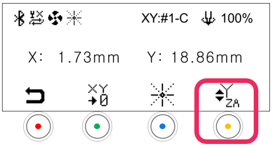
- Use the direction keys to set the laser pointer origin.
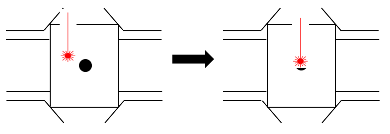
- Press the
 button to display save confirmation on the LCD window.
- Short press button: Temporary save (message guide X)
- Long-press and hold button (for more than 3 seconds): Permanent save
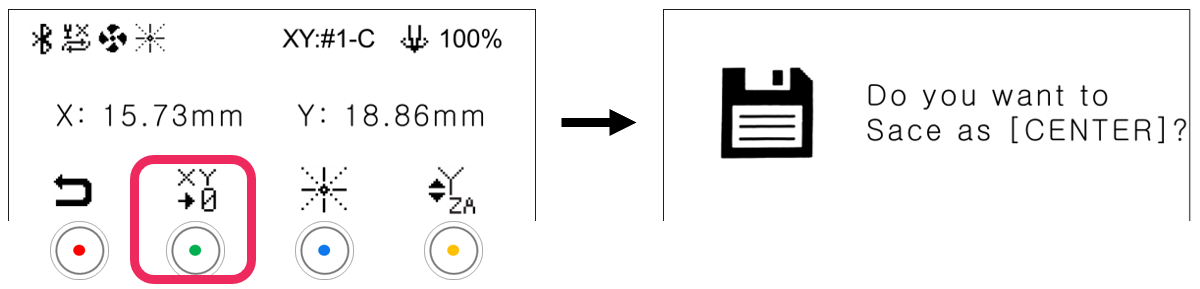
- Press the button to save the setting.
¶ 4. Saving New Clamp Origin Position
- Press button to enter menu mode.
- Use buttons. When 2. Select Origin menu appears on the LCD window, press button to run the menu.
- When menu appears on the LCD window (as shown below), use buttons to select “Clamp” and use buttons to select “Origin.”

- Long-press and hold the button (for more than 3 seconds) until it beeps to confirm that the setting is saved.
¶ 5. Chuck Finger Origin point
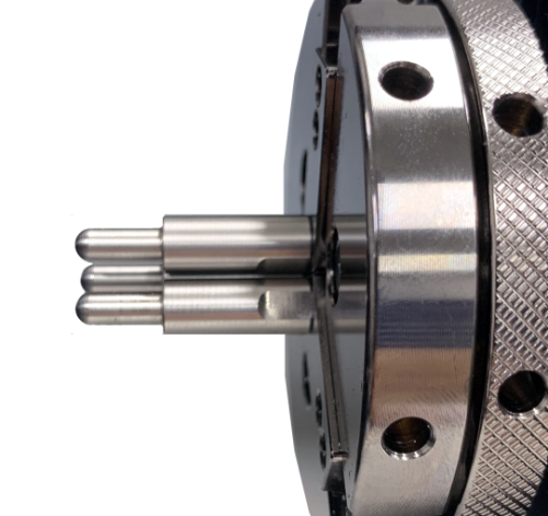
- Attach the chuck finger to the rotary clamp.
 |
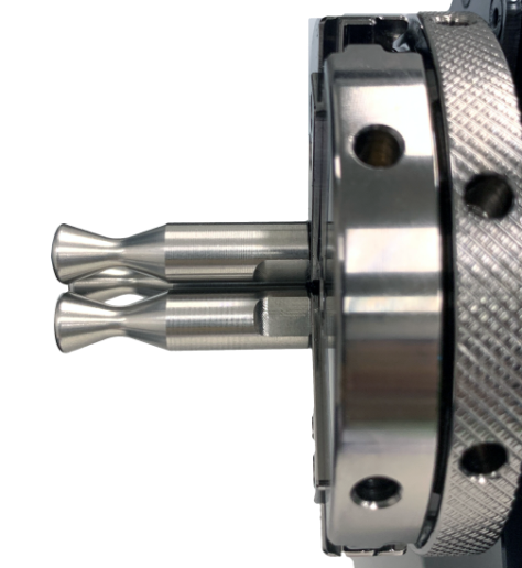 |
| Flat Chuck Finger | Round Chuck Finger |
- To enter the [Standby-Rotary] mode, press [Finger Mode] button.
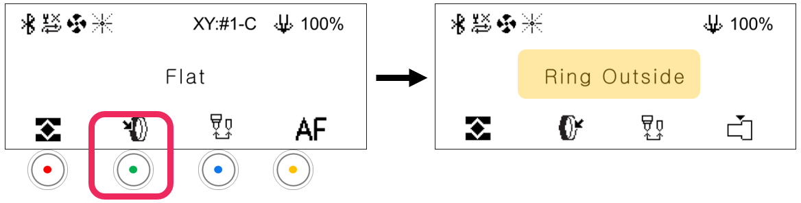
- Press button to switch to [Move mode-Rotary].
When the LCD window displays the following (as shown below), press [Laser pointer] button to turn on the laser pointer.
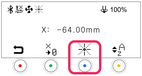
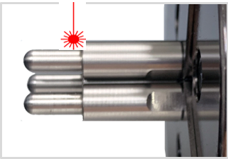
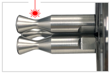
- Use the direction keys to match the laser pointer to the base point of each chuck finger as shown below.
 |
 |
| Flat Chuck Finger | Round Chuck Finger |
- Press the
 button to display save confirmation on the LCD window. And press button to change mode. (Flat finger → Round finger → cylinder).
- Short press button: Temporary save (message guide X)
- Long-press and hold button (for more than 3 seconds): Permanent save
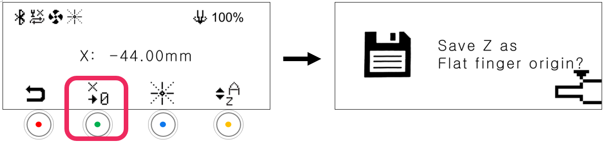
- Press the button to save the setting.
¶ 6. Rotary Clamp Origin point (Z axis)
- To enter the [Ring Inside] mode, press [Finger Mode] button.
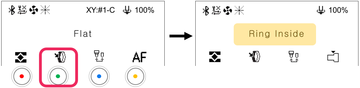
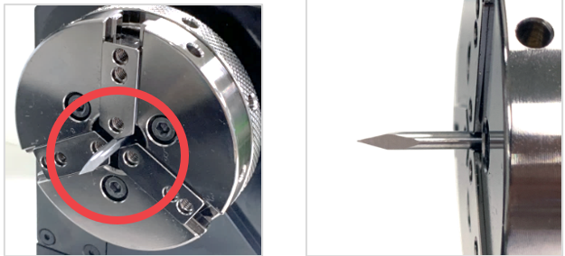
- Set the sharp tool into the rotary chuck as shown below.
- Press button to switch to [Move mode-Rotary].
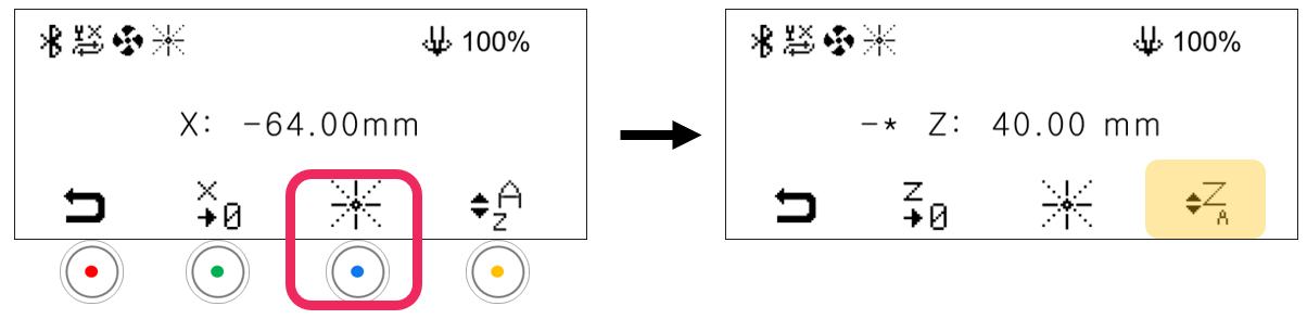
- When the LCD window displays the following (as shown below), press
 button to change the [Z-axis mode].
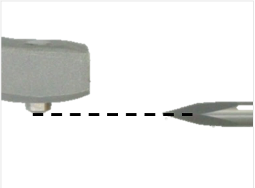
- Use buttons to horizontally align the tip of the engraving tool to the tip of the blade (as shown below). Use buttons to adjust the distance between tools. Be sure the tips are closer to each other.
- Press the
 button to display save confirmation on the LCD window.
- Short press button: Temporary save (message guide X)
- Long-press and hold button (for more than 3 seconds): Permanent save
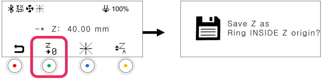
- Press the button to save the setting.
¶ 7. Camera calibration
| Bakelite plate (120x100x2t) |
 |
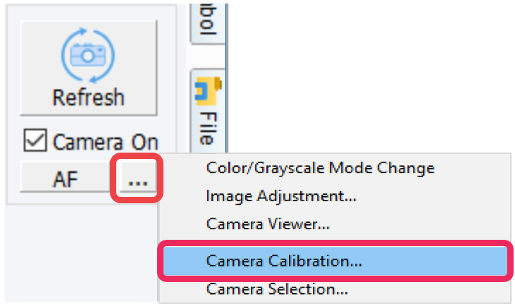
- Camera can be calibrated in the MagicEngrave program.
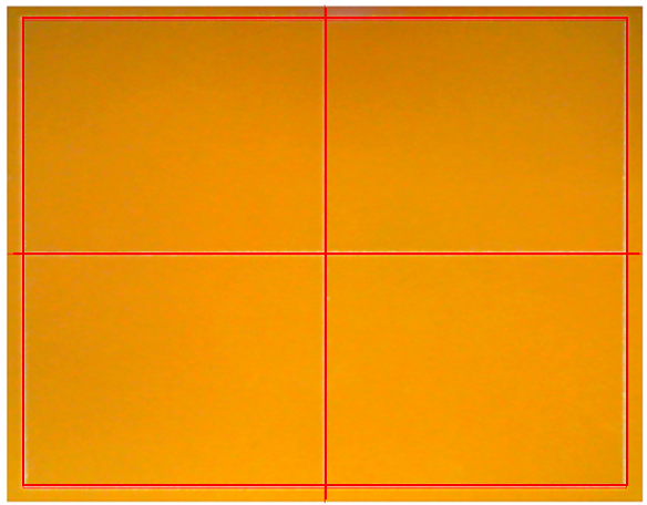
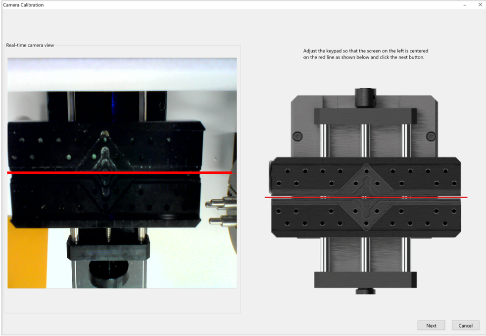
- Use the button to adjust the red line (that appears on the screen) to center of the clamp. Once the red line is adjusted to the center, click [Next].
- Place and secure the bakelite to the clamp. Set the calibration area to 90 x 70mm then click [Create Line]. Check the calibration results then click [OK].
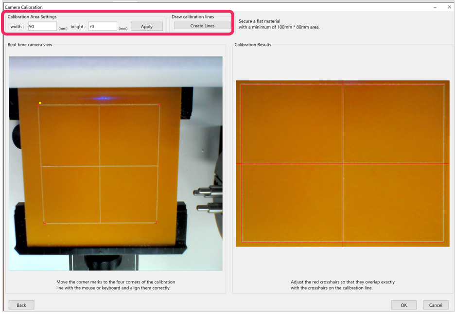
- Press and hold the button (for more than 3 seconds) until it beeps to start engraving. A rectangle will be engraved for calibration.
- Align the red corner marks to the calibration line corners with the mouse or keyboard.
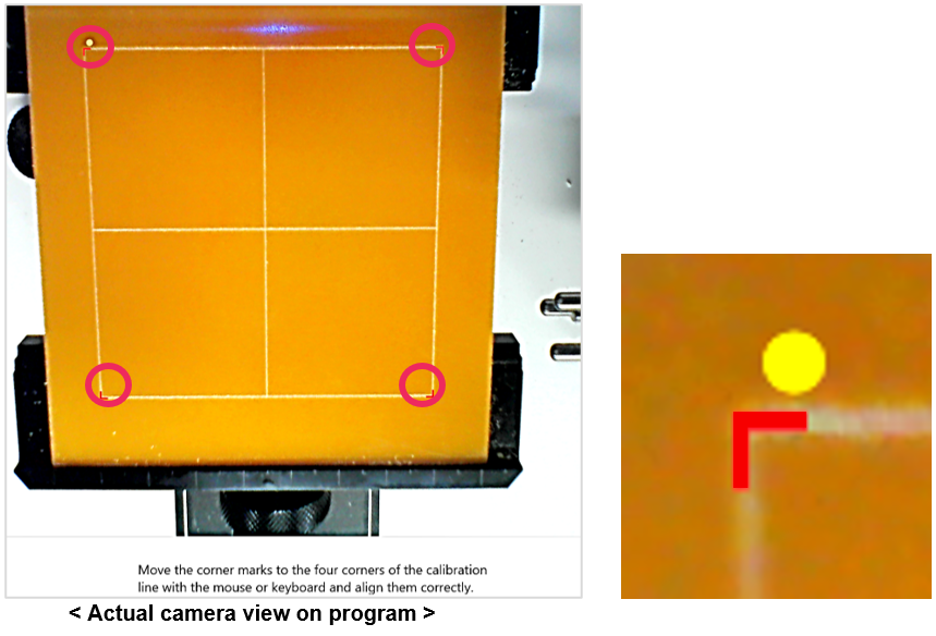
- Check the calibration results on the program. Be sure that the red lines are marked over the calibration lines. Click [OK] to complete the calibration.