¶ Contents
- 1. Marking Process
- 2. Photo Marking
- 3. Curved Materials Marking
- 4. Layout of text in a circle
- 5. Layout of text in a curve
- 6. Text Change
- 7. Template Creation
- 8. Saving as design sample
- 9. Auto change of serial number
- 10. Loading and editing image
- 11. Import a file SVG format
¶ 1. Marking Process
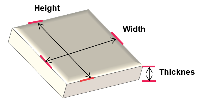
1. Measure the size and height of your material.
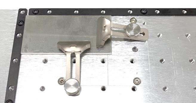
2. Place your material on the flatbed.
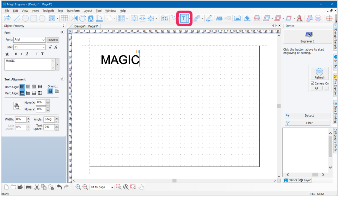
3. The selected template will appear on the screen. Click  [Text input] button then click at any target location to enter text.
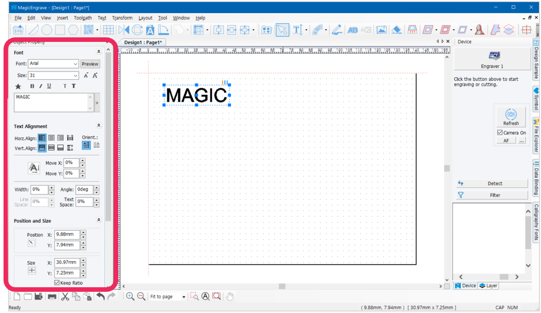
4. Once the text is completed, click  [Selection] button on toolbar. Enable the object selection mode to select the entered text then modify the size, font and thickness of the object.
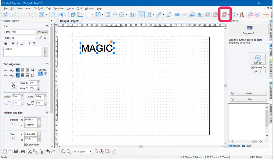
- Upon completing the design, click
 [Hatching toolpath].
✽Click icon on the top right of the screen for immediate marking without creating a Toolpath.
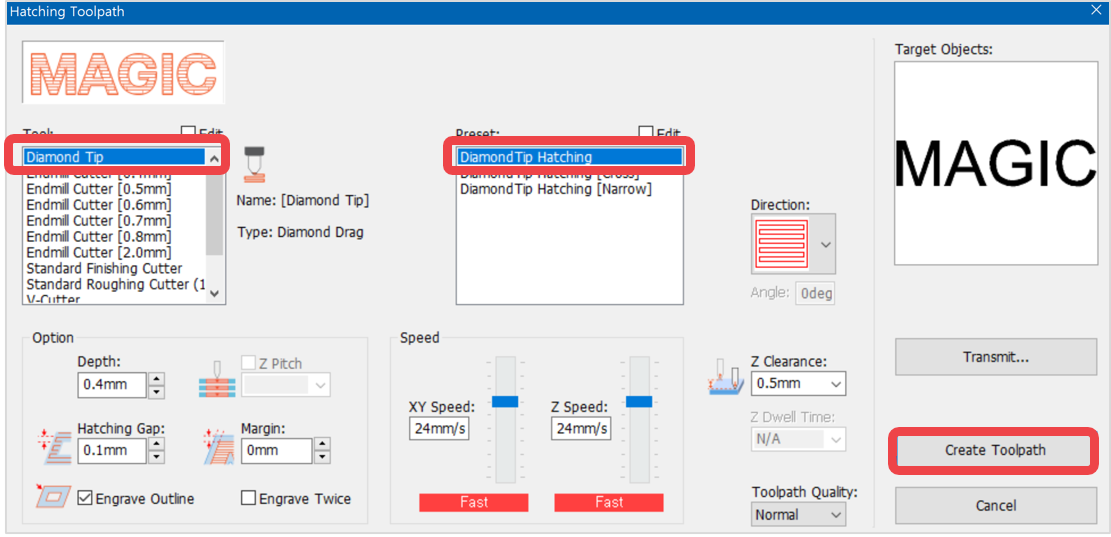
6. Select an engraving option and tool from “Toolpath” window and if necessary, designate gap and depth before clicking “Create Toolpath” button.
 |
 |
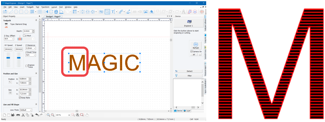
| -Scan line toolpath- | -Hatching toolpath- |
*For better engraving quality on large areas (e.g., large fonts or images) use “Scan line toolpath.” Although this may require more time to process.
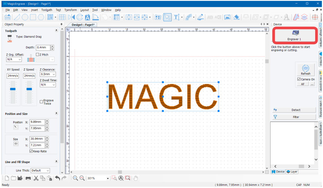
7. Toolpath object is created.
- Click button.
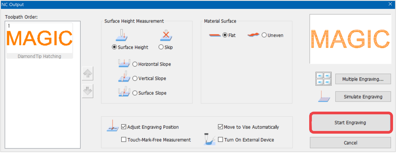
- Once “NC Output” window appears, specify how the engraving material is measured then click “Start Engraving” button.
- Once the tool is positioned to the center of the material and the laser pointer turns on, use the direction key buttons to position the laser pointer to the engraving area. The area that the laser pointer points to is where the actual engraving takes place.
 |
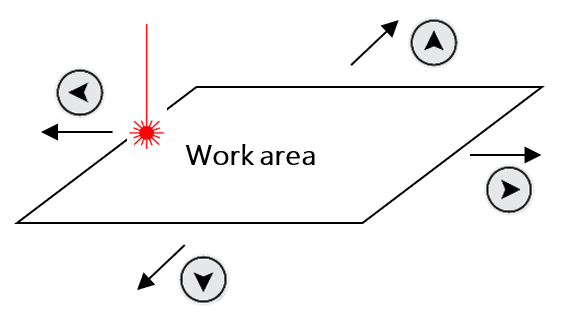
Press the direction key buttons to move the laser pointer to the left, top, right and bottom areas of the engraving area. (Long press to move the laser pointer farther). Check if the laser pointer points to the area on the material where you want to engrave. If the laser pointer is out of range, adjust the position using the direction keys.
The laser pointer automatically points to the area where marking takes place (based on the target location on the work area). When the direction key is pressed, the laser pointer moves to the area to be marked (left, top, right or bottom) from its target location. If the marking area needs to be adjusted to the left, press  key to move the pointer to the left. key to move the pointer to the left.
 |
- After positioning the laser pointer and determining the location of the engraving area, long-press and hold
 button (for more than 3 seconds) until it beeps to confirm that the machine is ready to engrave.
¶ 2. Photo Marking
What is Photo Marking?
Photo marking is a marking method that marks the shade of an image with dots.
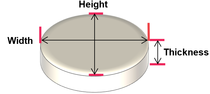
- Measure the size and height of your material.
- Place your material at the center of the clamp.
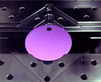
※Multipurpose Clamp ※Optional device; sold separately
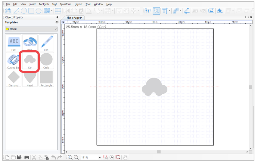
- Select a template that matches the shape or type of your material from the template category. Enter the size of your material then click “OK” button.
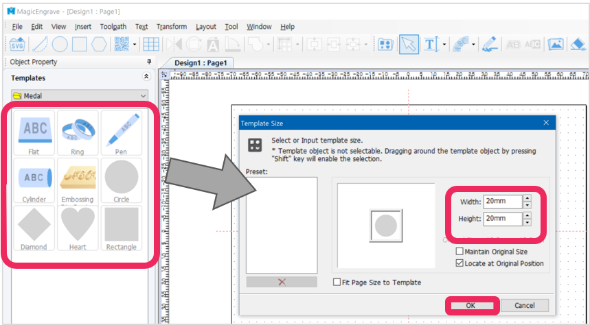
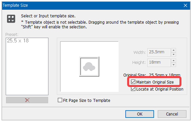
| Maintain original size | The actual size of the registered template is loaded; not the size entered. |
| Locate to original position | The template is loaded to where it was initially created. If this option is selected, the template is loaded at the center of work area. |
| Fit page size to template | The size of the page is adjusted to the size of the template. |
¶ [Load image]
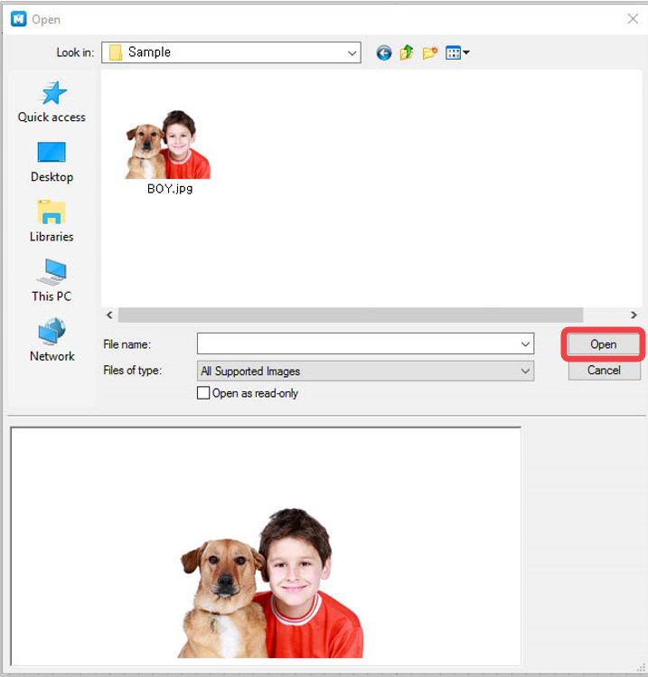
- Click
 [Image] to import an image for marking.
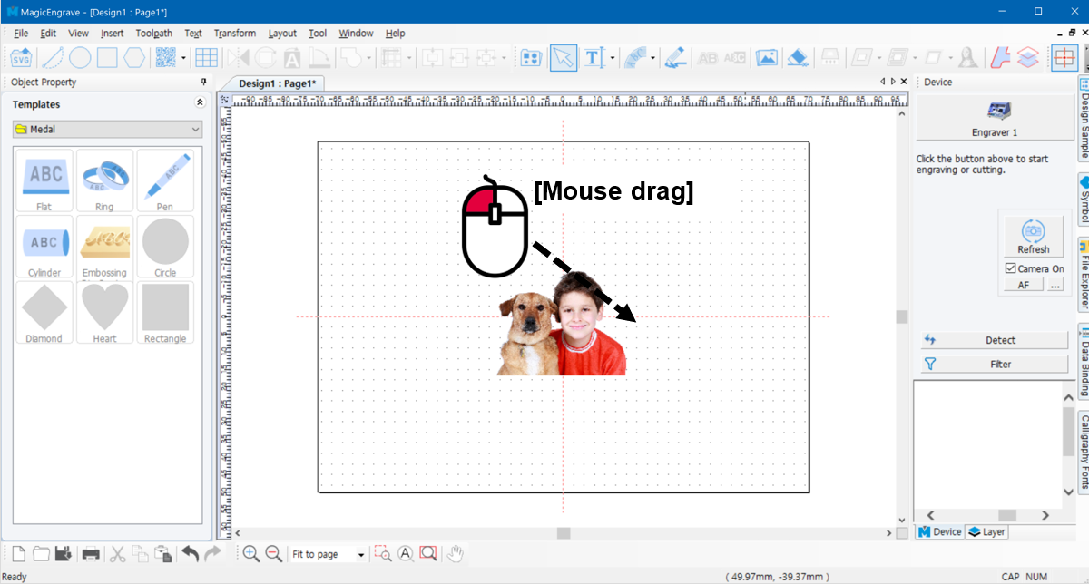
- Adjust the size and location of the image.
- [Clipping Mask] feature enables clipping or cropping of the target image. Drag the mouse over the image then create a shape.
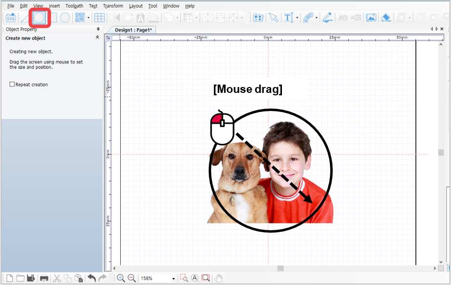
- Drag and hold the mouse to select the target image or select [Menu] → [Edit] → [Select All].
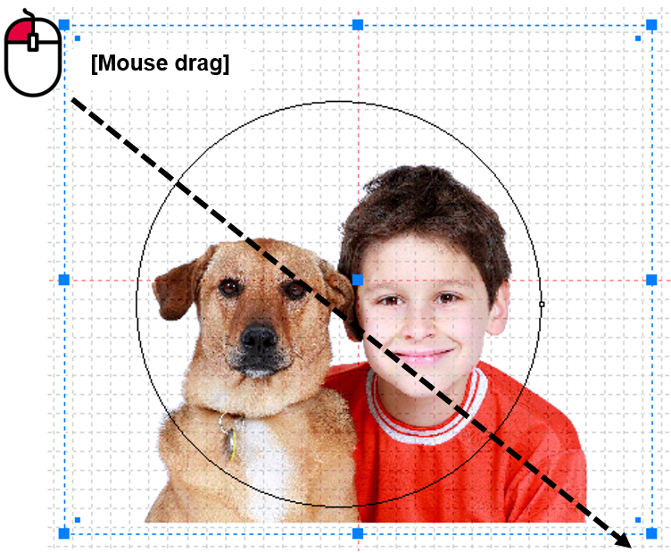
5. Then select [Menu] → [Transform] → [Make Clipping Mask]. Only the cropped image (target image) remains.
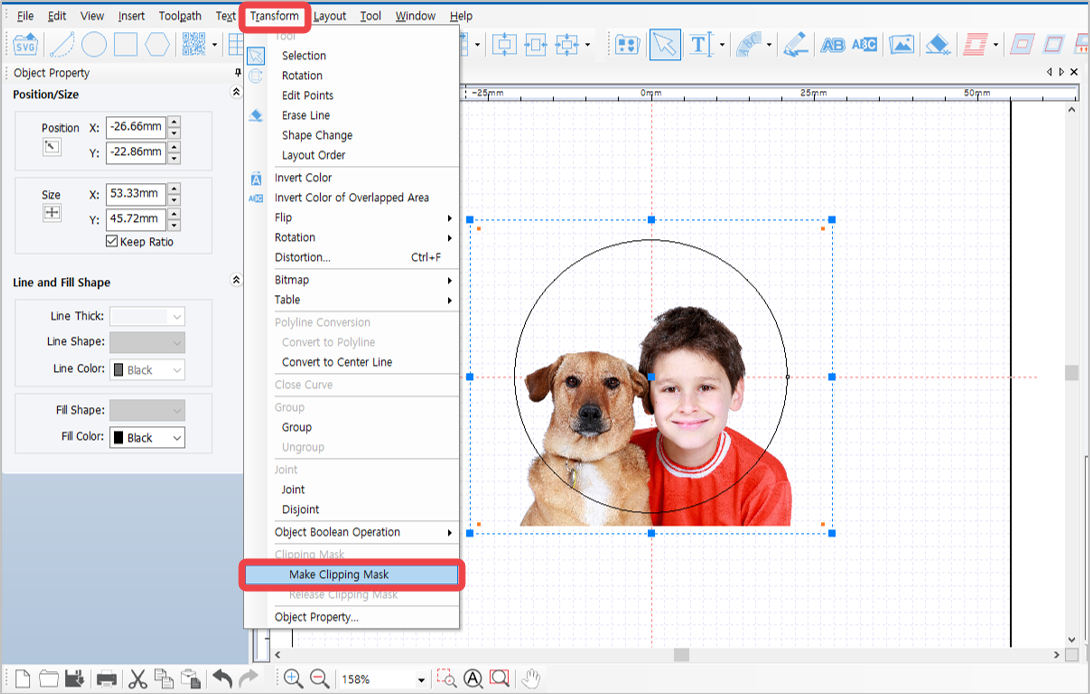
The original image is saved; not deleted or cropped out.
- Click
 [Photo Impact Engraving Toolpath] button.
✽Click button on the top right of the screen for immediate marking without creating a Toolpath.
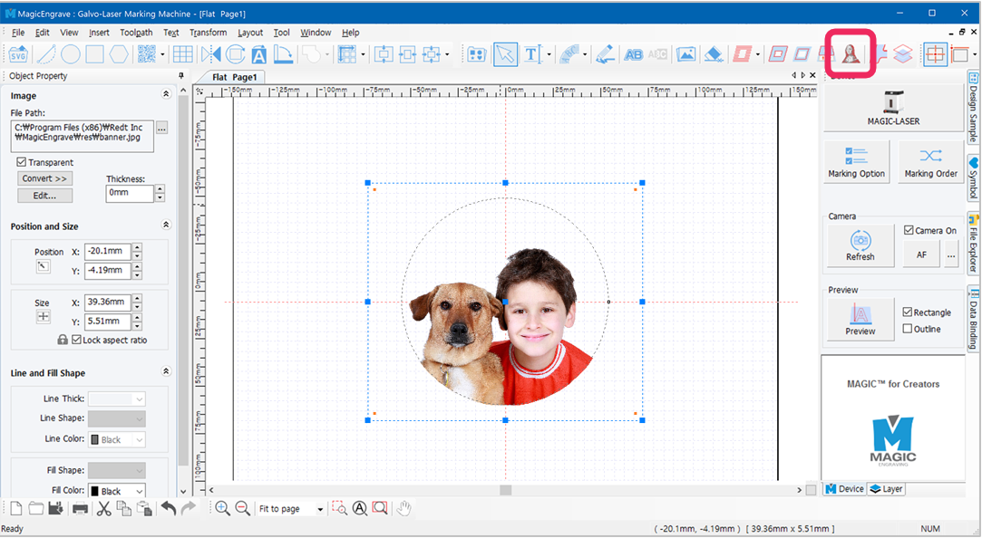
- Adjust marking options in photo marking option window.
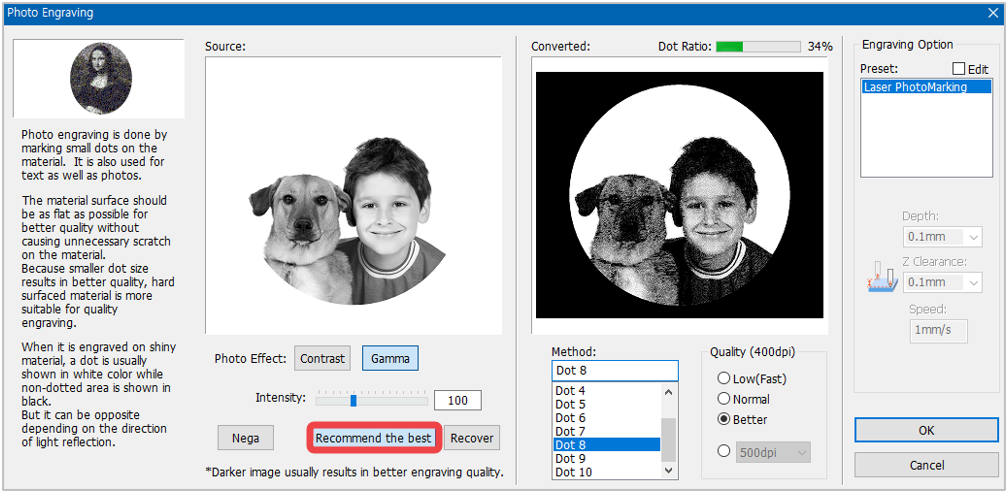
✽ The black area is not engraved; only the cropped image.
During photo marking process, the brighter area (white area) of an image is not visibly expressed with dots unlike the darker area where dots are highly visible with higher marking quality. Therefore, it is recommended to adjust the brightness of an image to darker. Normally, a dot ratio of 10-20% provides the best marking quality for a portrait. Take note that the image’s optimal conditions vary depending on the brightness of background of the image. Check image preview then adjust the image’s brightness and dot ratio. If ‘image adjustment’ is confusing, click “Recommend the best” button to automatically adjust the image.
- Click “OK” button to create a toolpath for photo marking. Set the marking option then click [Engraver] button.
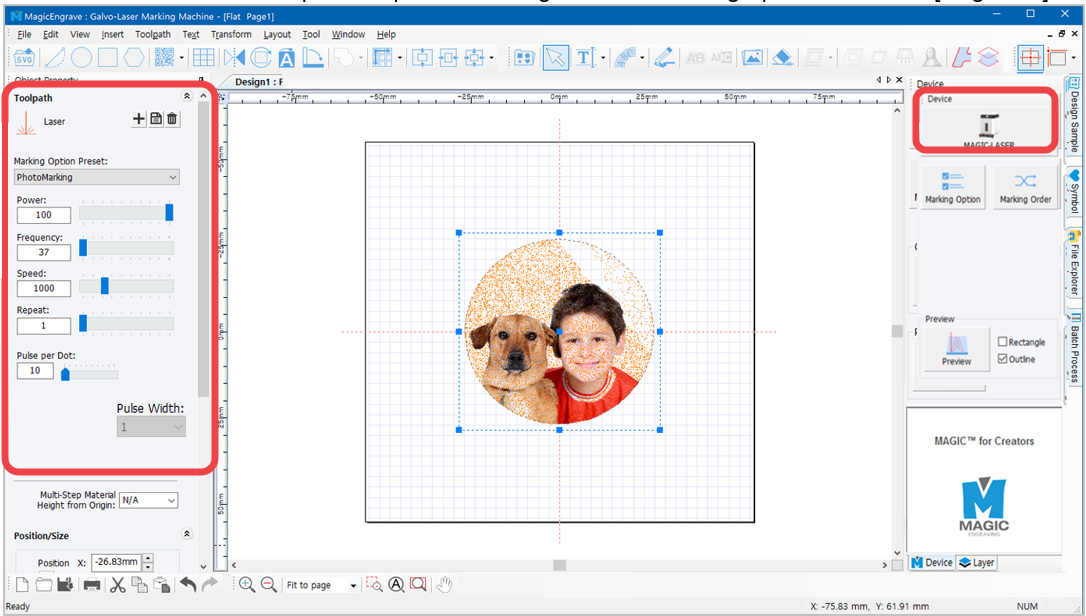
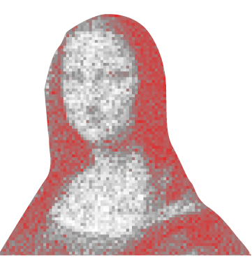
During marking process, the white area of the image appears with dots. The image result of the toolpath is shown as a negative image.
- Once the tool is positioned to the center of the material and the laser pointer turns on, use the direction key buttons to position the laser pointer to the engraving area. The area that the laser pointer points to is where the actual engraving takes place.
|
Press the direction key buttons to move the laser pointer to the left, top, right and bottom areas of the engraving area. (Long press to move the laser pointer farther). Check if the laser pointer points to the area on the material where you want to engrave. If the laser pointer is out of range, adjust the position using the direction keys.
The laser pointer automatically points to the area where marking takes place (based on the target location on the work area). When the direction key is pressed, the laser pointer moves to the area to be marked (left, top, right or bottom) from its target location. If the marking area needs to be adjusted to the left, press key to move the pointer to the left.
|
- After positioning the laser pointer and determining the location of the engraving area, long-press and hold button (for more than 3 seconds) until it beeps to confirm that the machine is ready to engrave.
¶ 3. Curved Materials Marking
Scratch on the surface of a curved material is likely to be caused by the tool touching the surface of the material when it moves. This can be avoided by entering the thickness of the material’s surface to set the Z-movement height automatically.
- Create a toolpath then click button.
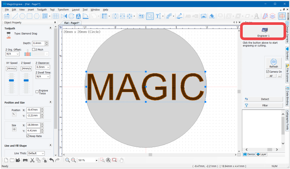
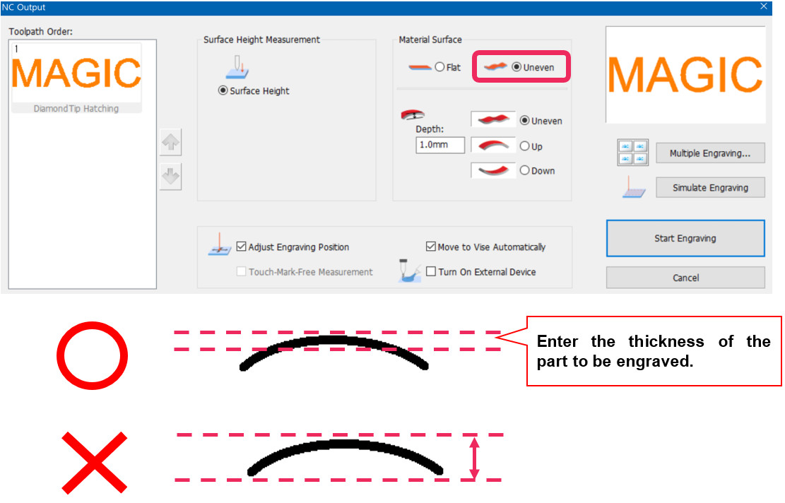
- Once “NC Output” window appears, click “Uneven” to see different kinds of curved materials. Select a shape that resembles the shape of the material then enter its thickness (the thickness of the area to which the engraving is applied) then click “Start Engraving” button.
¶ 4. Layout of text in a circle
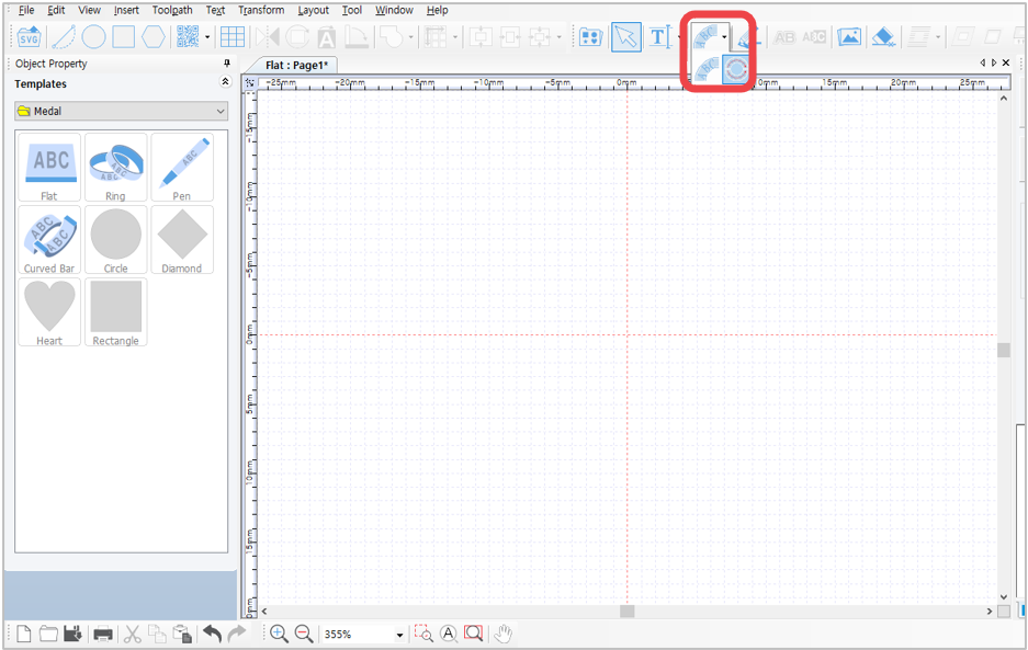
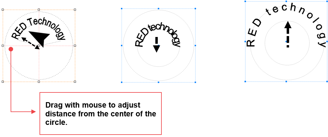
Texts can be arranged around a circle by using circular text object.
¶ Circular Text
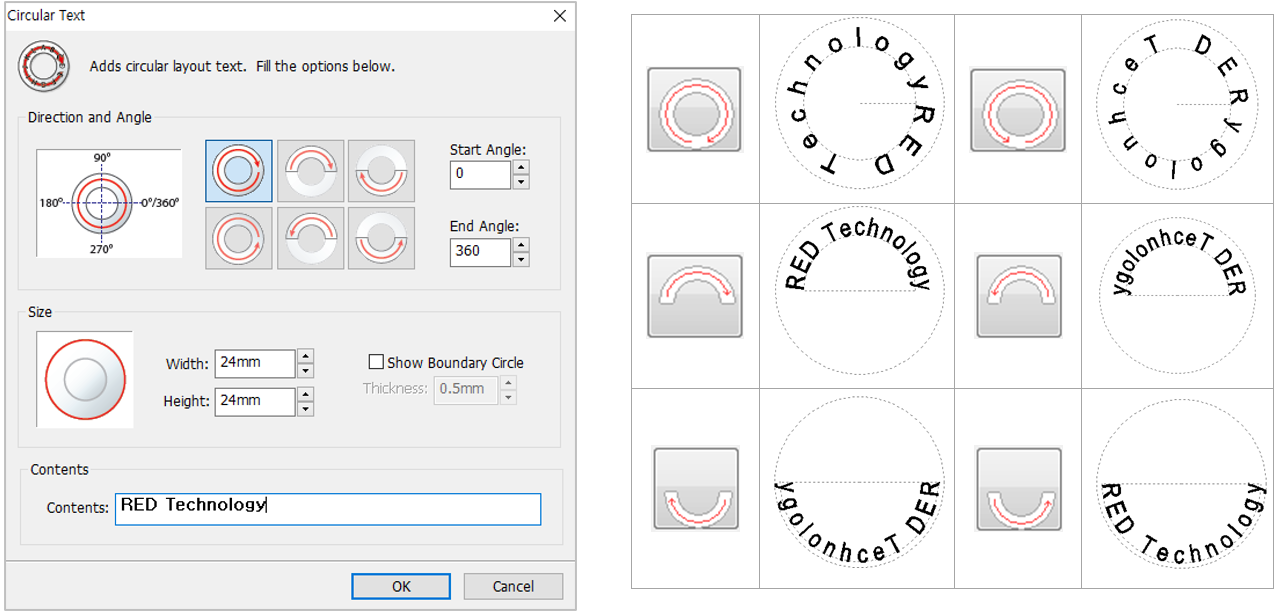
Click  button to display “Circular Text” window. Designate direction and angle, enter the size and text, then click “OK” button.
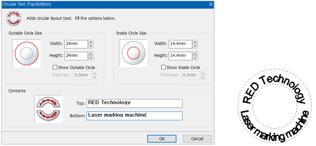
¶ Circular Text- Top/Bottom
¶ Adjusting layout angle
Drag the first character [R] or last character [y] in the text to adjust the angle of the layout.
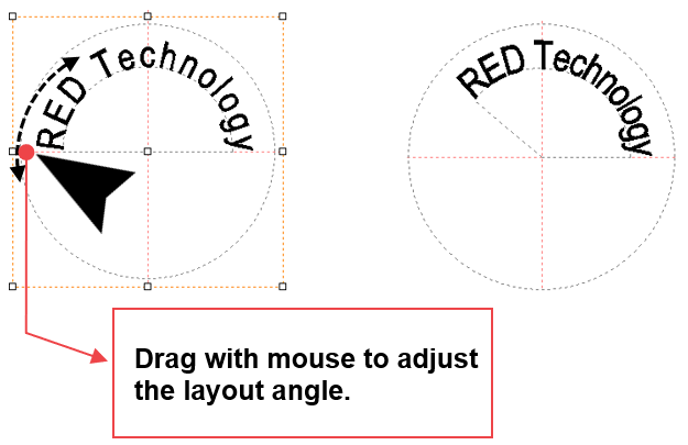
Drag other characters with the mouse to adjust the distance to the center of the circle.
¶ 5. Layout of text in a curve
- Click the
 [Line/Curve] button.
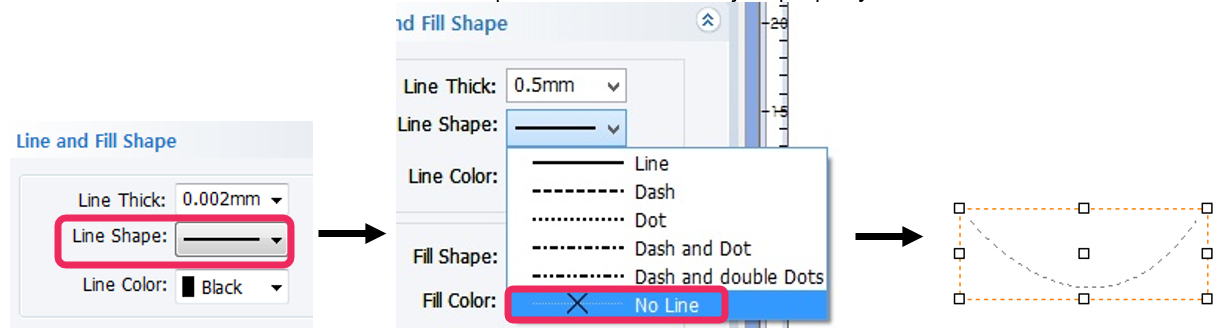
- Left-click to display the dotted lines then designate a distance.
Drag the mouse to make a curve appear then right-click to create one.

- Select “No Line” on the “Line and Fill Shape” window on the object property window.
- Click [Text Input] button then move the mouse cursor to the curve line. The cursor will change to text cursor as shown below.
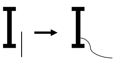
- When the cursor changes to text, click the curve line then enter the text.

¶ 6. Text Change
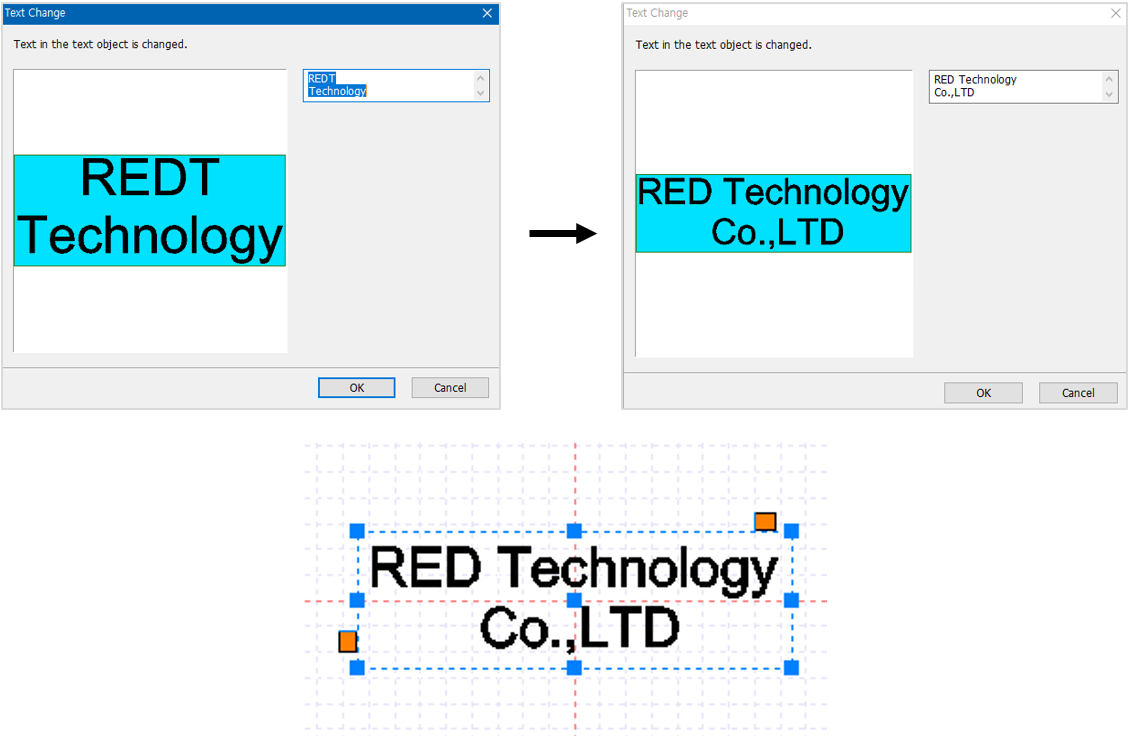
The content of a text can be changed by using [Text Change] feature.
Open a saved design sample, file or select the text objects entered on the work area. Click  [Text change] button or right-click with the mouse then select [Text Change] on the menu. Or, select [Menu] → [Text] → [Text change].
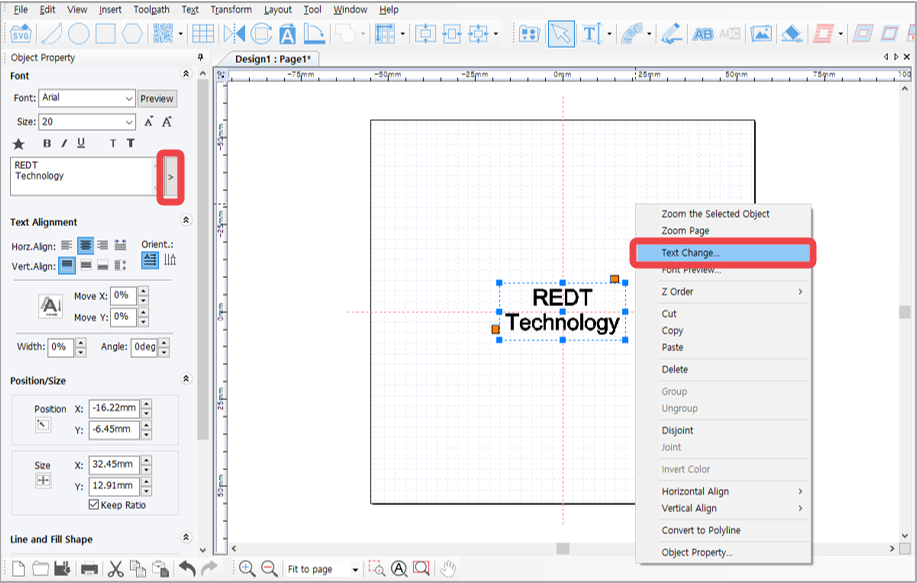
Change the content in the “Text Change” window then click “OK” button. The modified text will be shown on the screen.
¶ 7. Template Creation
Template is an image that corresponds to the material to be engraved by 1:1 ratio. Load a template similar to the shape of the material to be engraved then enter the text. This allows you to easily and conveniently position your text and determine its size. Templates such as circle, heart, square and diamond are available in the program, and users can freely add more templates. Templates can be created by using graphic programs like Illustrator, Photoshop and CorelDraw, or by loading images in SVG file format, jpeg, bmp, png, etc.
¶ Creating template 1
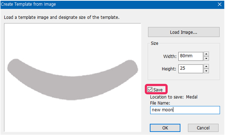
1. Select [Menu] → [Template] → [Create Template from Image].
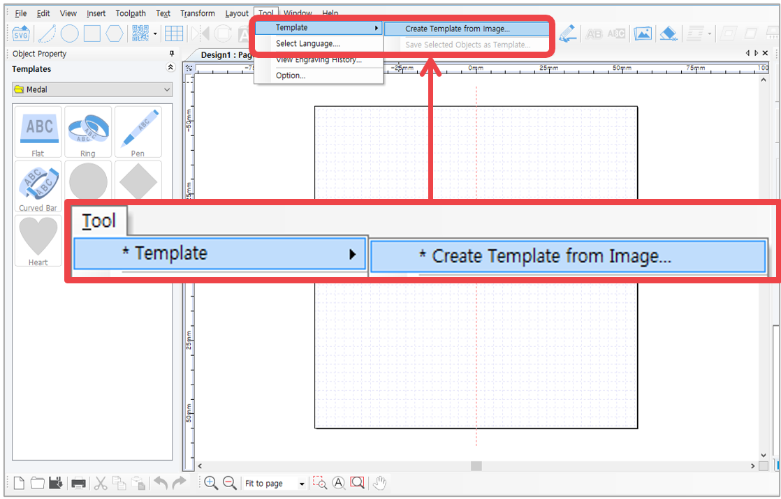
2. "Create Template from Image” window will appear.
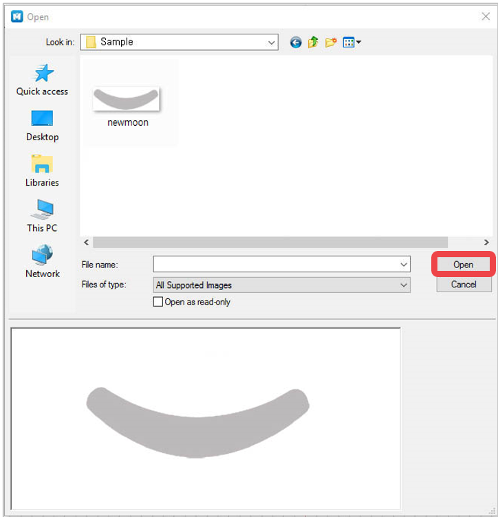
3. Select the image file (jpeg, bmp, png and etc.) from the “Open” window then click “Open” button.
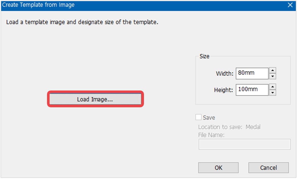
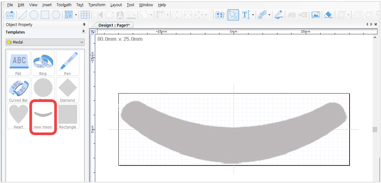
4. Enter the size of the template. Check “Save” to save the image as a template for later use then enter the file name. Click “OK” button to load the image as a template. The image will be saved as a template in the template library.
¶ Creating template 2
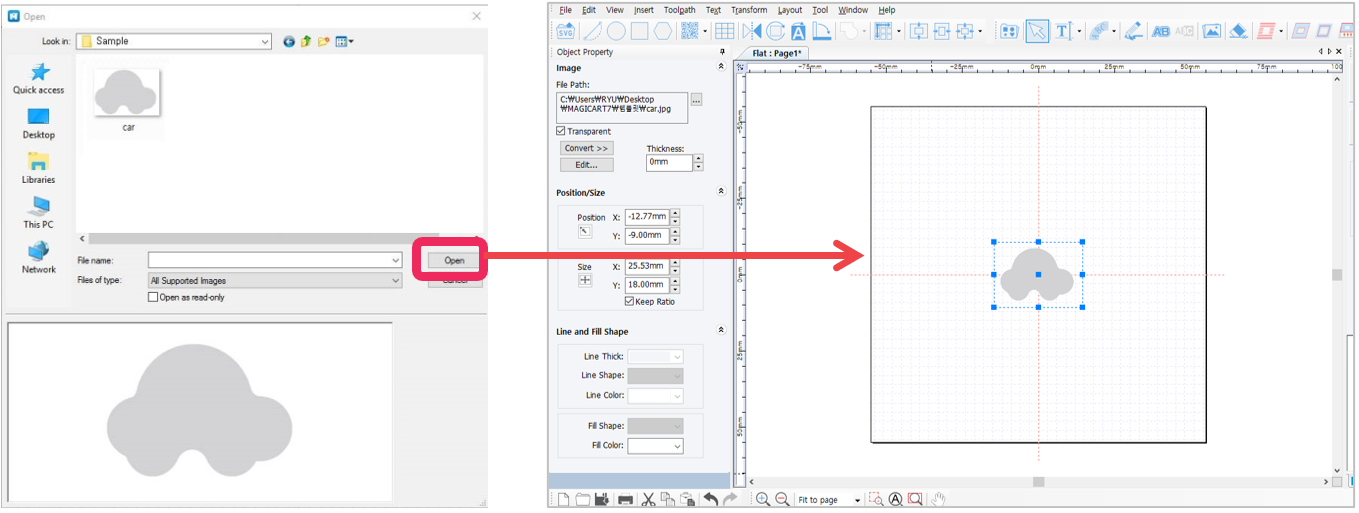
1. Click [Image] button to open an image file.
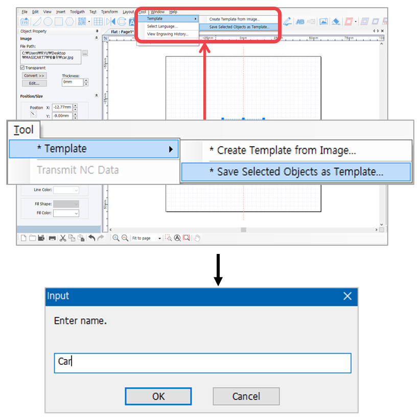
2. Select [Menu] → [Template] → [Save Selected Object as Template].
Enter a new template name in “Input” window then click “OK” button.
3. The saved template is added to the template library.
The saved template in the “Save Selected Object as Template” menu is saved based on the size designated on the screen. When loading a template, check “Maintain Original Size” so the template will be loaded based on the original size designated when the template was saved.
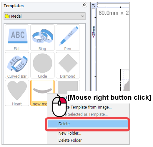
✽ Templates can be added or deleted. “Add” or “Delete” option can be selected by right-clicking in the template category window.
¶ 8. Saving as design sample
Edited texts, contents or designs can be saved as design samples for future use.
¶ Saving as design sample 1
1. Edit contents and select the objects.
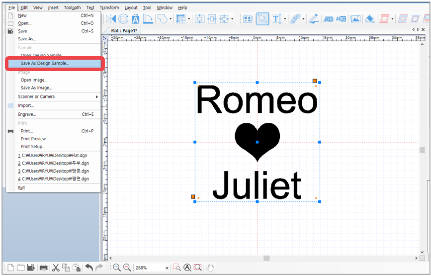
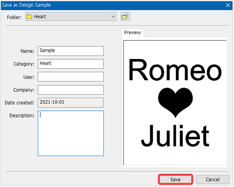
2. Click File [Menu] → [Save as Design Sample] then select a folder or create new folder.
Enter the name then click “Save.
¶ Saving as design sample 2
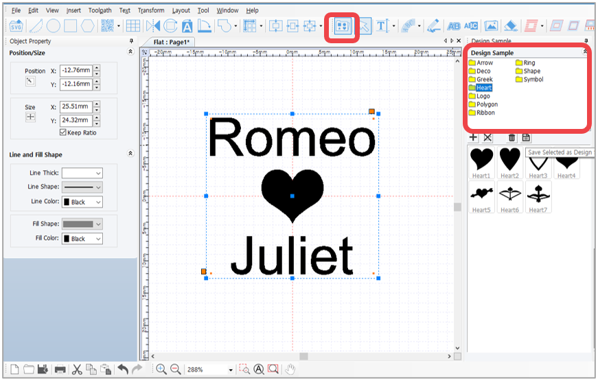
1. Select the objects then click [Design Sample] button. Select a folder from the design sample library window to save the created design.
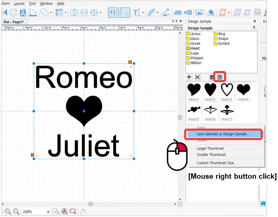
2. Click [Save selected image as sample] or right-click the design sample image then click “Save Selected as Design Sample” on the menu.
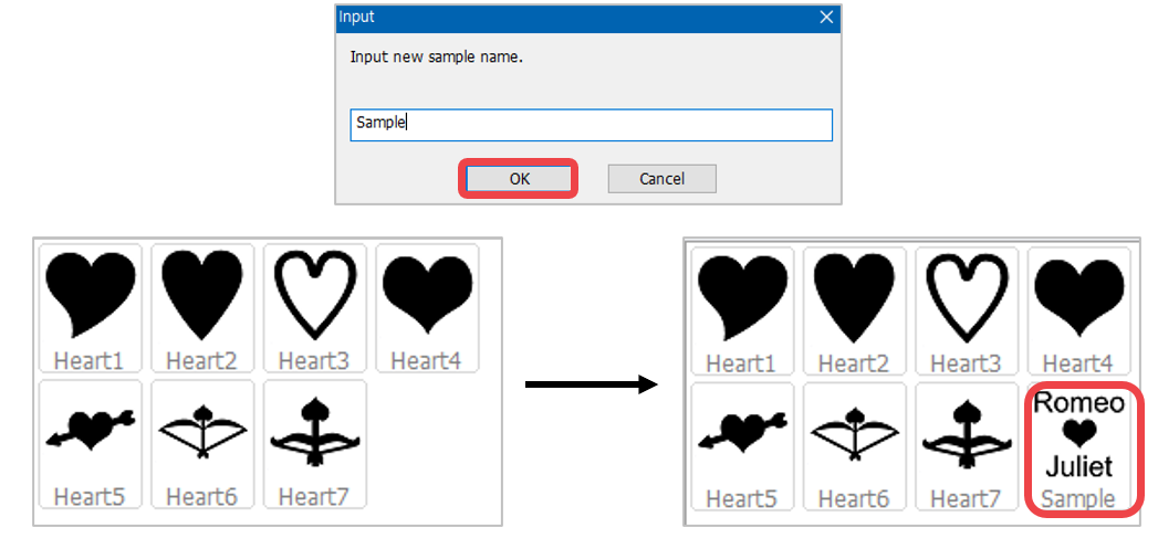
3. Enter the name of the design created then click “OK” button. The design will be saved in the design sample library.
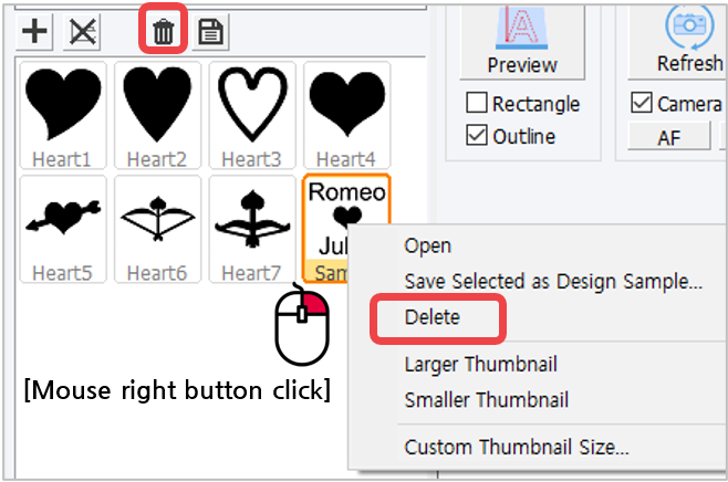
✽ Right-click in the design sample window to see more features. The design sample can be deleted by
right-clicking in the design sample window then select [Delete] on the menu.
¶ 9. Auto change of serial number
Use this function when changing numbers by certain unit.
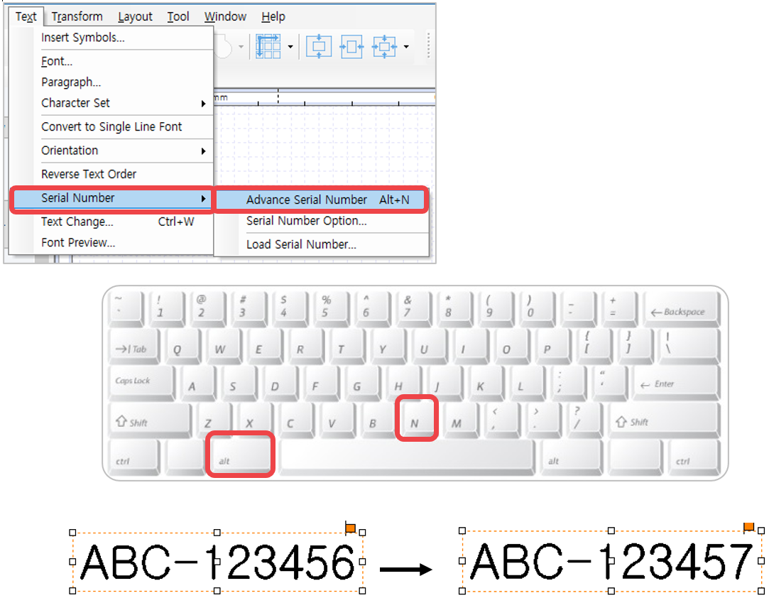
1. Edit the font and size of text object with a number then press “Alt+N” key on a keyboard, or select [Menu] → [Text] → [Serial Number] → [Advance Serial Number] to change the number automatically.
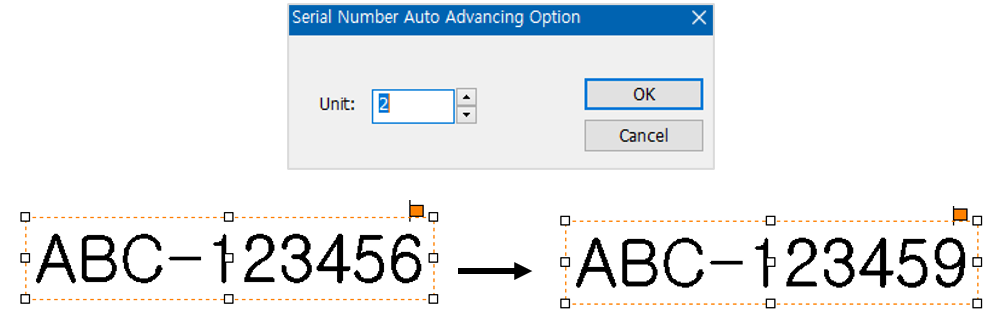
2. Select [Menu] → [Text] → [Serial Number] → [Serial Number Option] then enter a unit from the “Serial Number Auto Advancing Option” to change the serial number based on the assigned unit automatically.
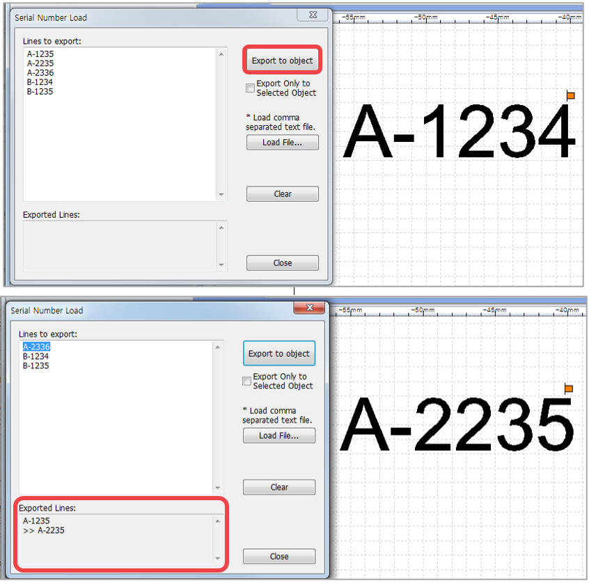
3. If the serial number is not consistent, select [Menu] → [Text] → [Serial Number] → [Load Serial Number].
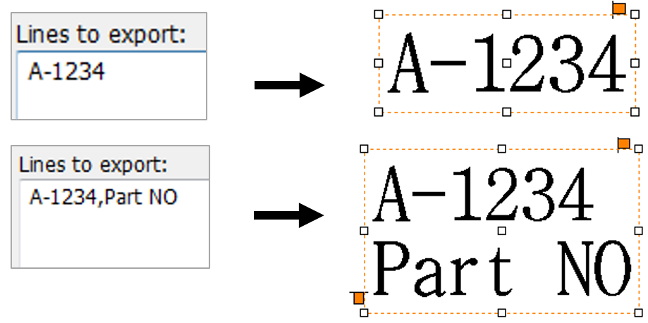
Enter serial number in the “Lines to export” field or click “Load File” button to load from a file (.txt or .csv file format). Once the serial numbers are loaded, click “Export to object” button. The text on the selected text object is automatically changed, and the serial number is deleted from the list. The deleted numbers will be shown in the “Exported Lines.”
Serial numbers can be loaded from a file separated by a comma (.csv) or text file (.txt).
Each row of the file is recognized as one serial number, and the contents of each row separated by a comma are shown in the next line.
¶ 10. Loading and editing image
¶ 1) Loading an image
This program provides a function to load various types of image files. Supported image files are as follows.
| BMP | Windows or OS/2’s bitmap graphic file |
| GIF | CompuServe graphic file |
| JPG/JPEG | JPEG bitmap graphic file |
| PNG | Portable Network Graphics bitmap graphic file |
| PCX | Z Soft PC paintbrush bitmap file |
| TIF/TIFF | Tagged Image File Format bitmap file |
| WMF | Windows meta file |
Image file can be loaded through the following methods.
1. Select [Image] on the toolbar or select [Menu] → [Insert] → [Image].
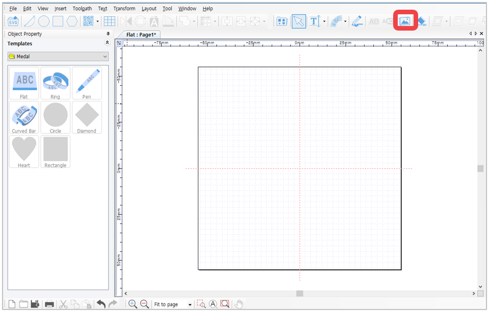
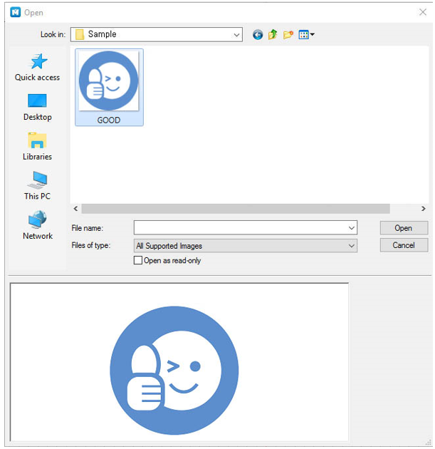
2. When “Open” window appears (as shown in the picture below), select the image to load then click “Open” button.
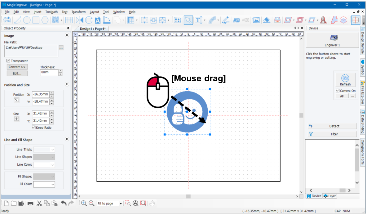
3. Drag the work area with the mouse to load the image according to desired size.
The machine can only engrave single-color images; not multi-color images. Multi-color images should be converted to single-color (1 bit) image.
¶ 2) Converting to single-color image
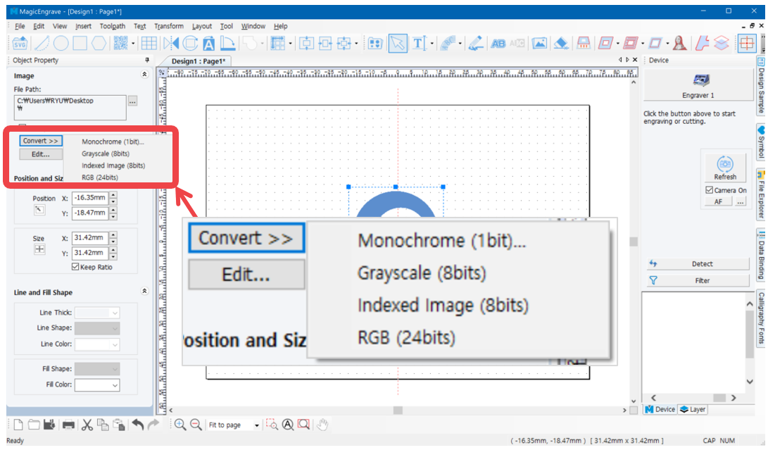
1. Select the image you want to convert. Click “Convert” button in the image object window then select “Monochrome (1bit).”
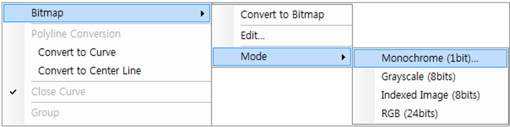
Or select the Transform menu → Bitmap → Mode → Monochrome (1bit).
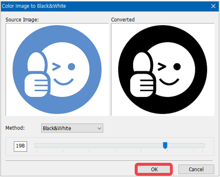
2. When “Color Image to Black & White” window appears, move the slider to adjust the level of color then click “OK” button.
¶ 3) Editing image
Loaded image can be edited via “Paint” program in Windows.
Select the image object to be edited then right-click to select “Edit” or, select [Menu] → [Transform] → [Bitmap] → [Edit].
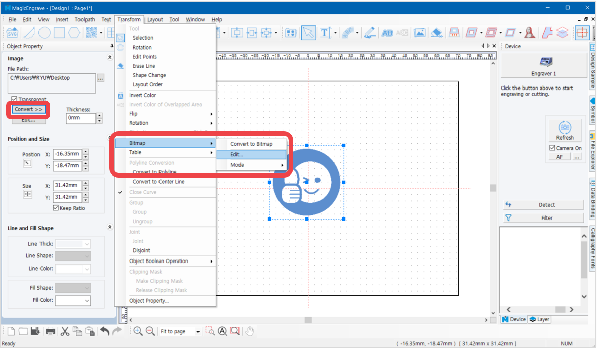
Click [OK] to run Windows Paint program.
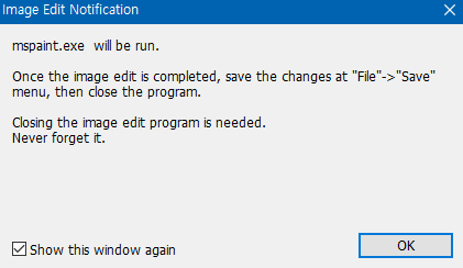
Then “Image Edit Notification” will appear.
Once editing is completed, click “Save” from Paint File menu then close the program to apply the changes.
¶ 11. Import a file SVG format
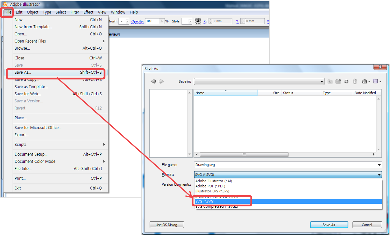
MagicEngrave supports vector graphic files in SVG format. If a design is created in programs like Illustrator or CorelDraw, the design can be loaded as long as it is saved as SVG file.
1. Select File menu → Save As from Illustrator program to save a file in SVG format.
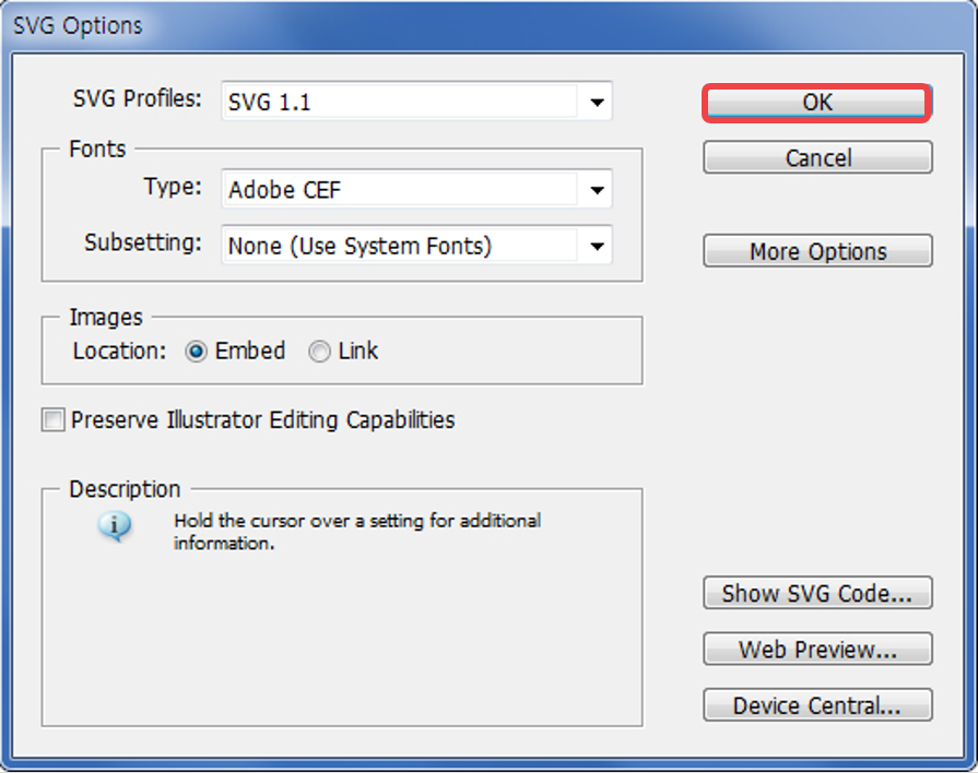
2. When SVG option window appears, click “OK” button to save changes.
3. Click [SVG] button to load the SVG file.
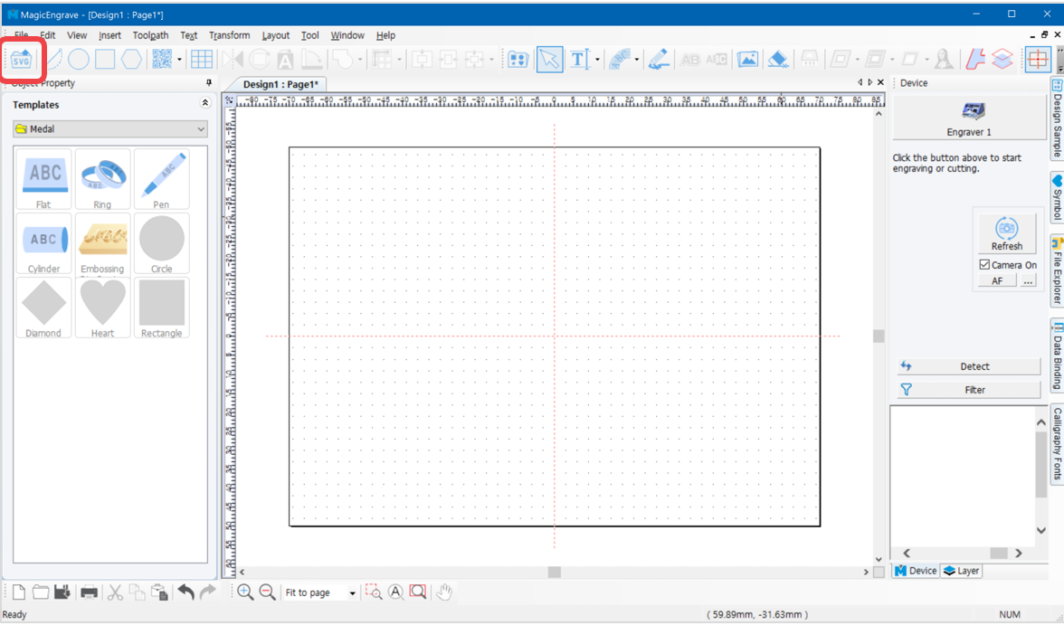
4. Or select [Menu] → [File] → [Import…] to import a file.
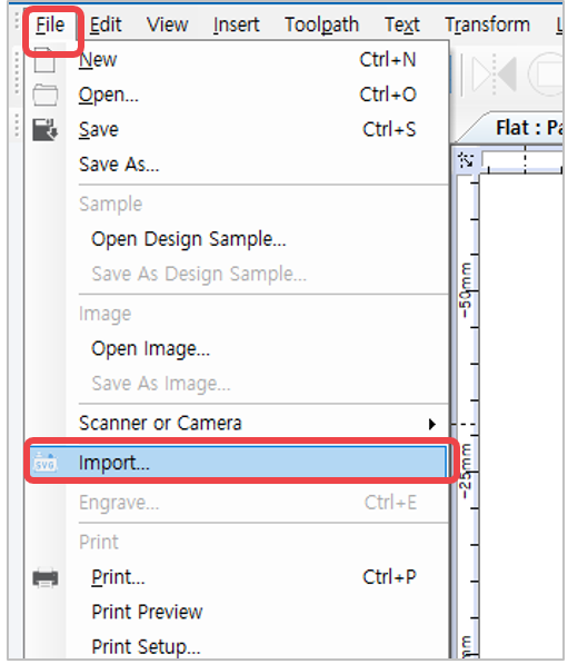
5. Once the file is imported, click the work area to display the image.