¶ Contents
- 1. Machine Descriptions for the L3 Prime
- 2. Clamp
- 3. Keypad
- 4. Display
- 5. Status Indicator
- 6. Air assist nozzle
¶ 1. Machine
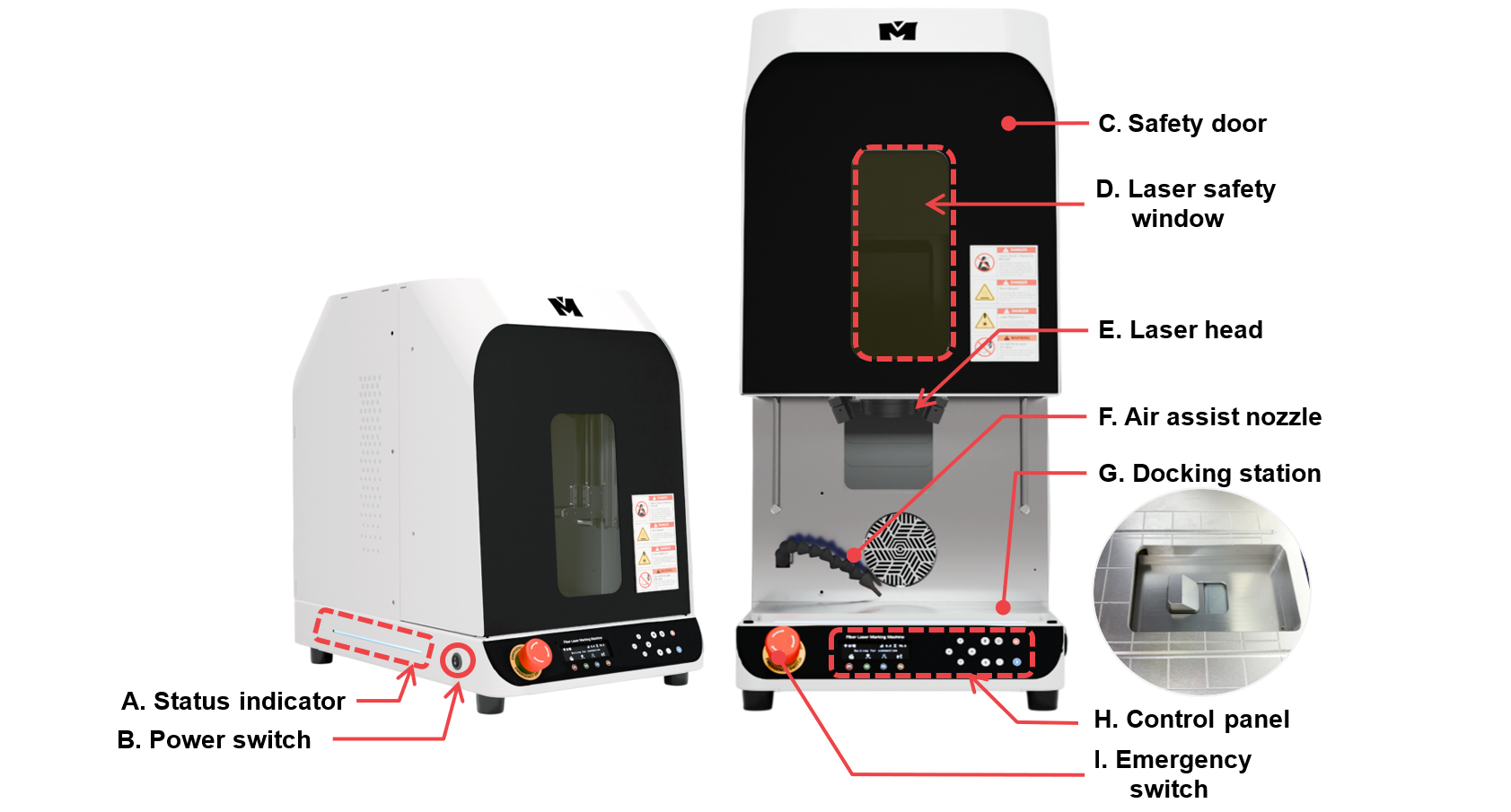
| A | Status Indicator | Shows the status of the device via blinking interval |
| B | Power Switch | Turn on/off the power switch. |
| C | Safety Door | Opens/closes the cover automatically. ※The cover automatically opens once the program is connected. |
| D | Laser Safety Window | Protects the eyes from being exposed to laser light. ※Wavelength protection: 1064nm/Optical density: OD6 |
| E | Scan Head |  Laser Source Do not stare at the specular/diffuse reflection of laser. It may result in blindness. |
| F | Air assist nozzle | Air assist nozzle with airflow control ※Air assist nozzle is sold separately. |
| G | Docking station | Connects the rotary clamp to the machine. |
| H | Control Panel | Controls the power button and the manual control for regulating engraving operations. |
| I | Emergency Switch | Stops the machine during emergency. |
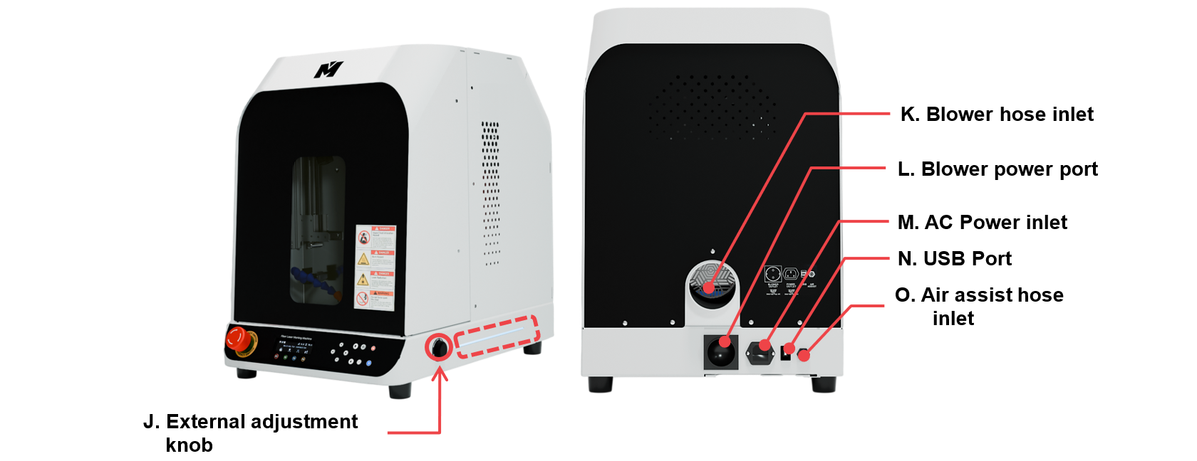
| J | External Adjustment Knob | Adjusts the position of the rotary clamp with a finger chuck handle. |
| K | Blower Hose Inlet | Connects the blower hose to the outlet to remove dusts and debris produced during marking operation. |
| L | Blower Power Port | To supply power to the blower by connecting it to the machine.(110~220V/2A) ※Auxiliary Power Device must be used if the external blower has more than 2 Ampere. |
| M | Power Port | To supply power to the machine. ※Use a grounded outlet only. Do not plug the machine into an ungrounded outlet. |
| N | USB Port | To connect USB cable to PC. |
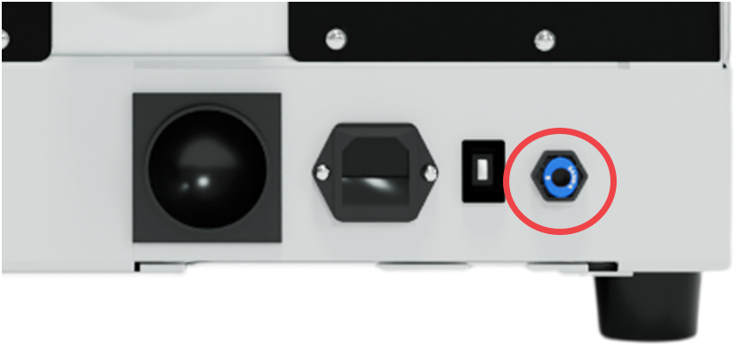
| O | Air assist hose inlet | Ø6 air hose connection port |
¶ 2. Clamp
※Work area: 110x110(mm)
※The grid guide lines can be used to check the position of workpiece on the work area.
[How to use the clamp]
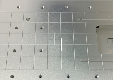
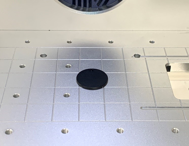
Place your material on the center of the work area.
※The grid guide lines on the work area appear similar to MagicEngrave grid guide lines on the screen.
¶ 1) Clamp
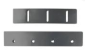
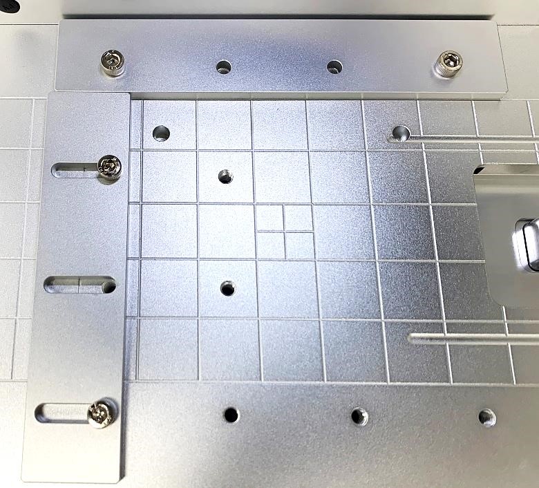
The clamp set is used to hold thin materials in place.
| Clamp (CL-22) |
 |
1SET |
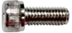
| Clamp Bolt (M5-12mm) (TL-512N) |
 |
4EA |
Place the clamps at a desired location on the work area then screw the bolts.
¶ 2) Medal Clamp
※Medal clamp is sold separately.
| Medal Clamp (CL-16) |
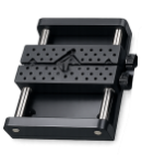 |
1EA | For holding materials with various shapes in place. |
| Pin(3Ø) (CM-04) |
 |
6EA | To secure materials with irregular shapes. |
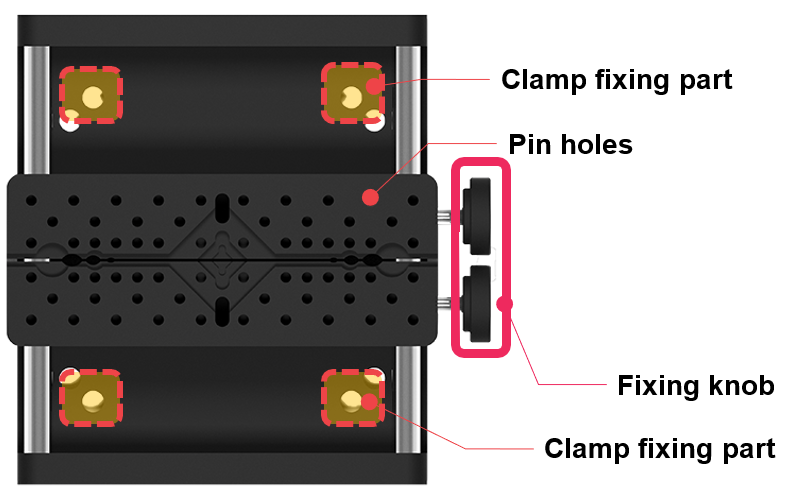
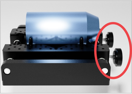
The clamp that holds the medal clamp is a step type. Set the medal clamp to the step type clamp to match the size and thickness of the material. To secure the material (tighten the gap), lift the clamp bar then turn the fixing knob to the right.
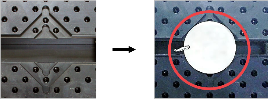
Marks may be left on the material if fastened tightly.
- Insert the clamp fixing pins (RP-0615) into the holes to secure the medal clamp.
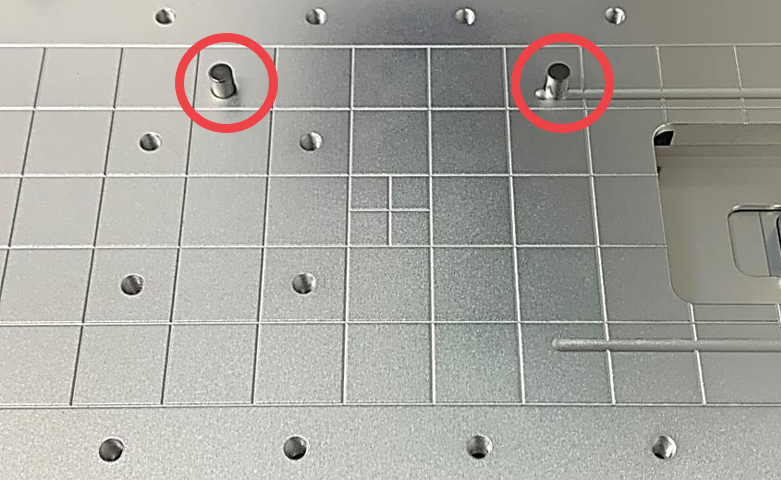
- Attach the medal clamp to the clamp fixing pins.
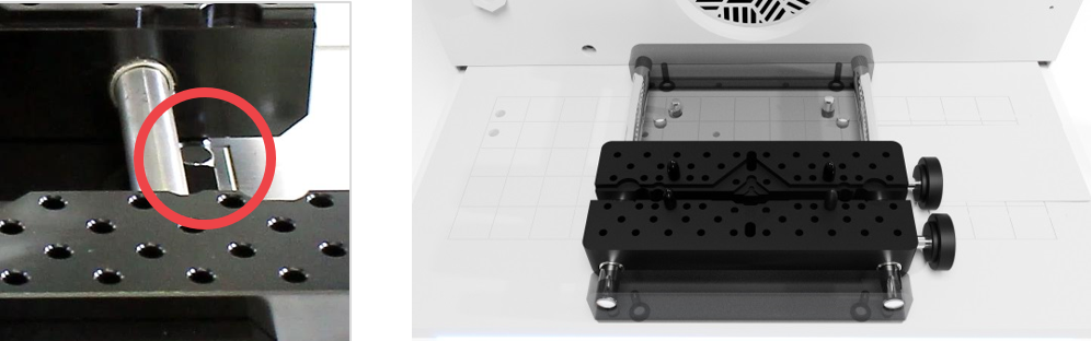
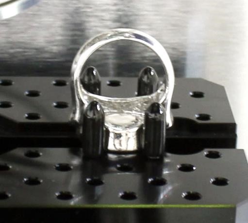
- Use the clamping pins to firmly hold materials with irregular shapes in place. To secure the clamping pins to the clamp, simply insert the pins into the pin holes then fasten them.
- Turn the fixing knob clockwise to secure the material.
¶ 3) Medal Clamp(Center fixing type)
※Medal clamp (center fixing type) is sold separately.
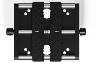
| Medal Clamp (Center fixing type) (CL-17) |
 |
1EA | For holding materials with various shapes in place. |
| Pin(3Ø) (CM-04) |
|
6EA | To secure materials with irregular shapes. |
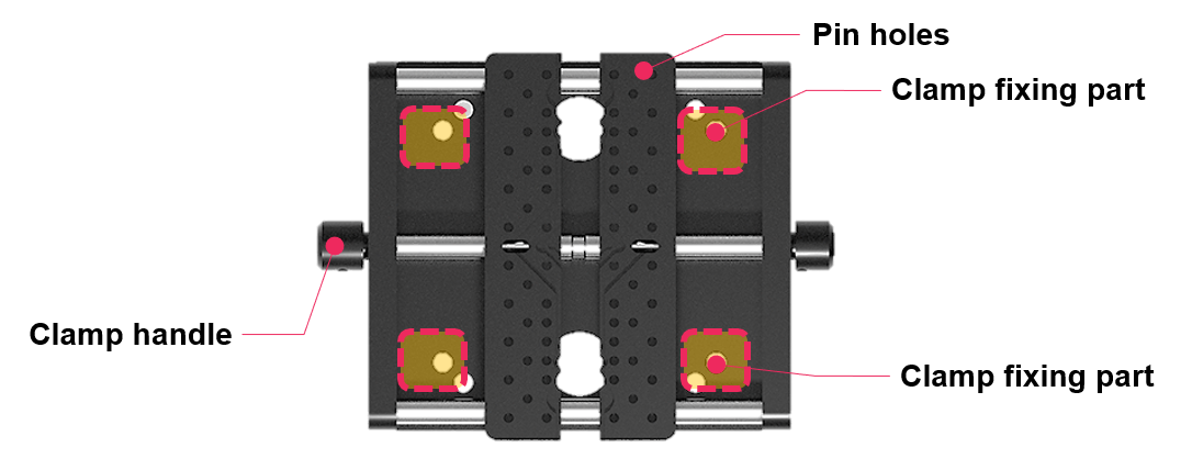
The clamp that holds the medal clamp is a step type. Set the medal clamp to the step type clamp to match the size and thickness of the material. To secure the material (tighten the gap), lift the clamp bar then turn the clamping knob to the right.
Marks may be left on the material if fastened tightly.
- Insert the clamp fixing pins into the holes to secure the medal clamp.
- Attach the medal clamp to the clamp fixing pins.
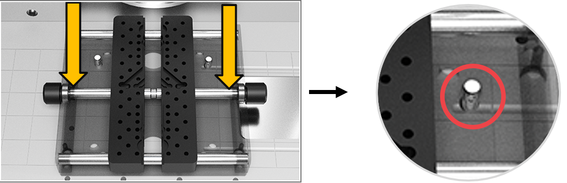
- Use the clamping pins to firmly hold materials with irregular shapes in place. To secure the clamping pins to the clamp, simply insert the pins into the pin holes then fasten them.
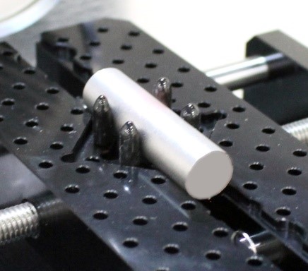
- Turn the clamping knob clockwise to secure the material.
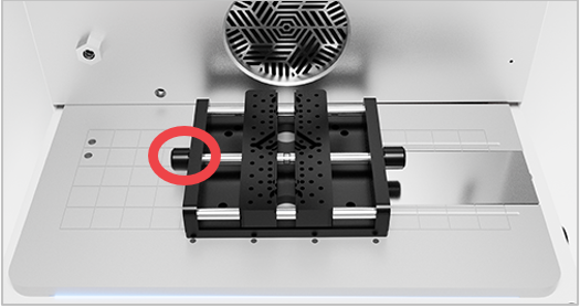
¶ 4) L-type Clamp
※L type clamp is sold separately.

Set the material against the fixing bracket. Be sure to place it properly.
¶ Origin Point Setting
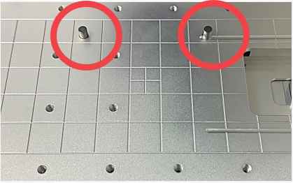
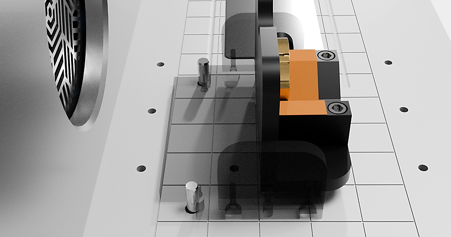
Set and position the L type clamp right at the center of the work area. The final alignment becomes the origin point of the L type clamp. Once the origin point is set, it is easy to return the L type clamp to its original position even after removal. If the vertical clamp is removed, the origin point must be set again.
- Insert the clamp fixing pins (RP-0615) into the holes to secure the L type clamp.
- Attach the L Type clamp to the clamp fixing pins.
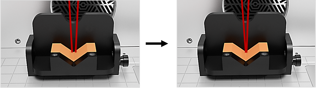
- Set the focus using the direction key (Z)

 buttons.
- Once the focus is set, check whether the L type clamp is properly set or not. Adjust the position of the L type clamp if the focus is not properly set at the center.
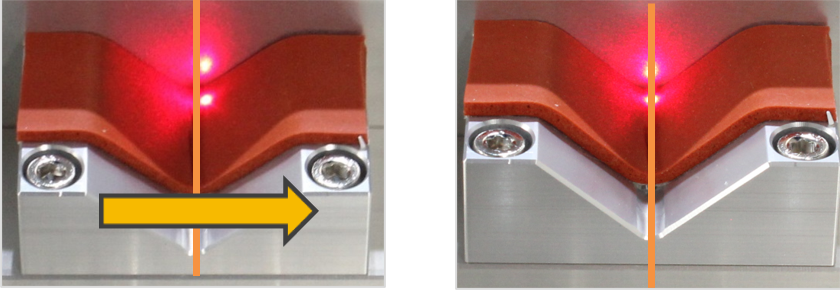
¶ Material Focus Setting
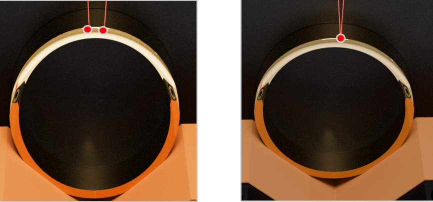
- Place the material properly on the clamp.
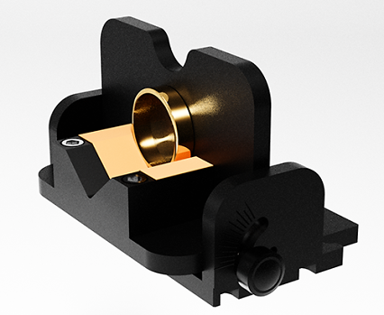
- Set the focus using the direction key (Z) buttons.
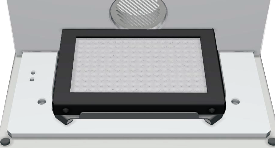
¶ 5) Honeycomb Clamp
※Honeycomb table is sold separately.
| Honeycomb Table (CL-21) |
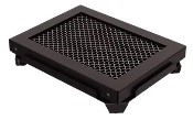 |
1EA | For holding materials in place for cutting process |
| Honeycomb Table Tray (LMC-15T) |
 |
1EA | Tray for Honeycomb Table . |
- Place the honeycomb table on top of the honeycomb table tray.
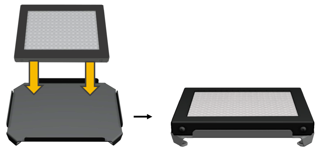
- Position the honeycomb table on the machine.
¶ 6) Rotary Clamp
※Auto tilt rotary clamp is sold separately.
| Anti-drop pin (6Ø) (18mm) |
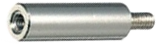 |
1EA | To secure the rotary clamp and to prevent it from falling during operation. |
| Finger Chuck Handle (CP-31) |
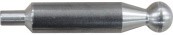 |
2EA | Handle for tightening/widening rotary clamp ※Also see external adjustment knob |
| Finger Chuck (8mm) (CL-33) |
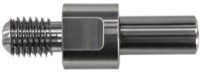 |
3EA | For holding rings in place when marking the inside or outside. |
| Finger Chuck (4mm) (CL-31) |
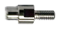 |
3EA | For holding rings in place when marking the inside or outside. |
| Finger Chuck (2mm) (CL-30) |
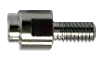 |
3EA | For holding thin rings in place when marking the inside or outside. |
| Finger Skin (CP-41) |
 |
1SET | For protecting finger chuck. |
| Finger Chuck Spanner (CP-21) |
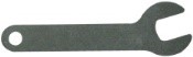 |
6EA | For tightening/unscrewing the finger chuck. |
| Auto Tilt Rotary Clamp (CL-15) |
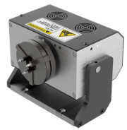 |
1EA | For holding ring materials in place. ※4mm chuck finger is included. |
| Setting tool | 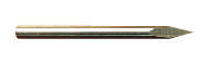 |
1EA | For setting rotary origin. |
* Optional (Purchased separately)
| Finger Chuck (6mm) (LMC-05-6) |
|
1EA | For holding materials with various shapes in place. |
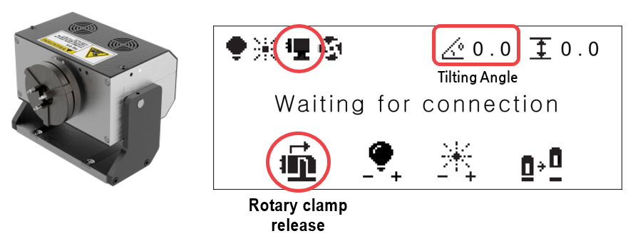
When using the rotary clamp auto tilting function, set the tilting origin to the 0 degree. (See [Machine setting] -5. Rotary origin for further details)
¶ How to connect the rotary clamp
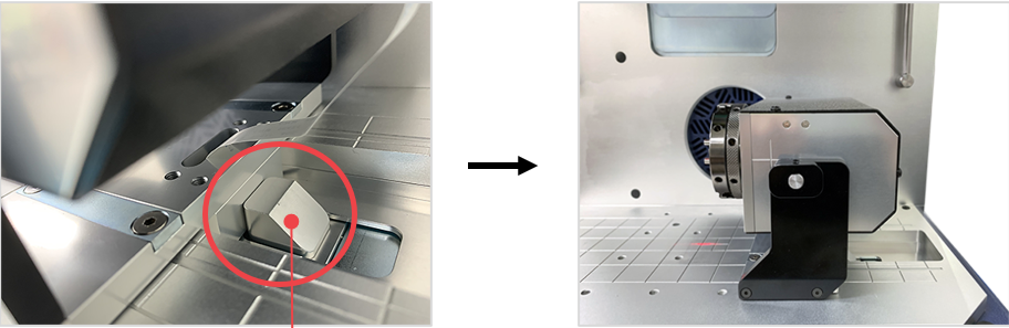
- Place the rotary clamp on the docking station and slide it to the left.
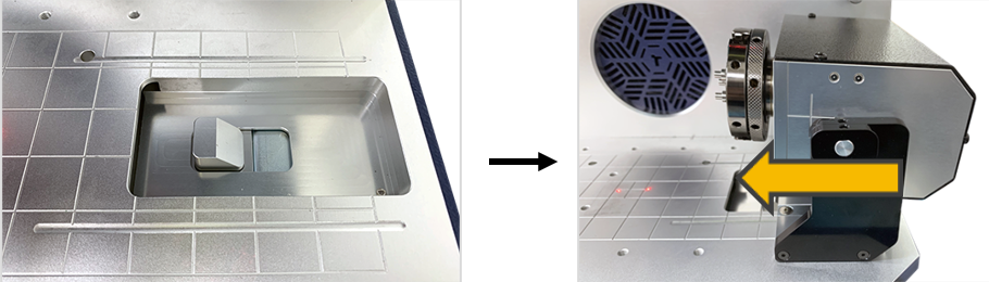
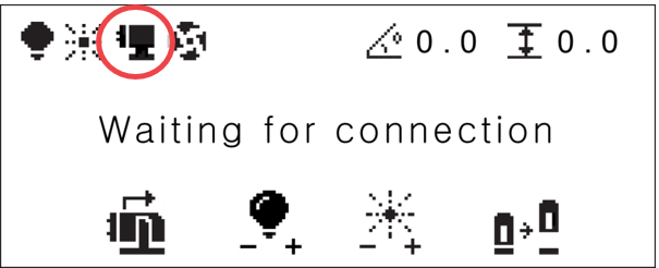
- Push the rotary clamp completely to the left until the push button fully lifts then beeps. Once the clamp is connected to machine, the machine will automatically recognize the device then it will begin to perform the initial operation.
- A mounting icon will appear on the screen.
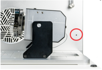
- Insert the anti-drop pin into the work area to secure the rotary clamp and to prevent it from falling during operation.
Anti-drop pin (6Ø) (18mm)
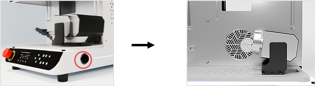
- Use the external adjustment knob (on the right side of the machine) to slightly adjust the position of the rotary clamp from left to right/right to left.
¶ How to disconnect the rotary clamp
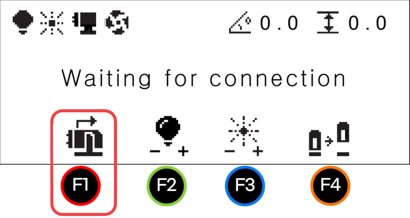
- Press the rotary clamp release button to disconnect the rotary clamp.
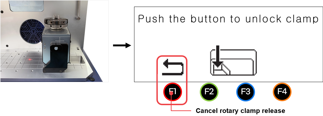
- The rotary clamp will be tilted to 90 degrees. Follow the instruction that will appear on the screen.
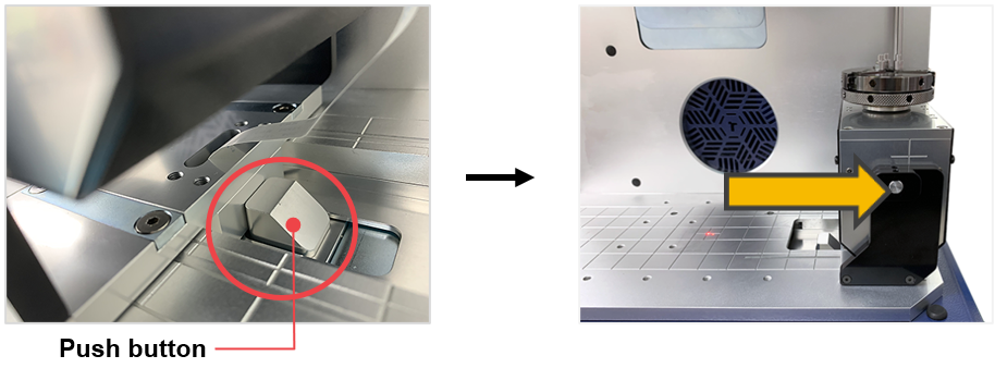
- Press the push button to release the rotary clamp then slide it to the right to put it aside.
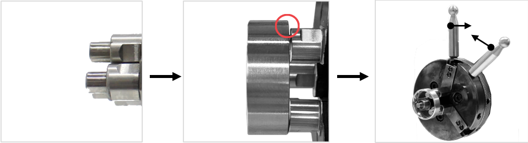
¶ How to secure the ring when marking the outside
Put the ring on the finger chuck then move the finger chuck handle in opposite directions to secure the ring.
¶ How to secure the ring when marking the inside
Insert the ring into the finger chuck then move the finger chuck handle in opposite directions to secure the ring. Use the finger chuck handle to widen or tighten the gap of the finger chuck.
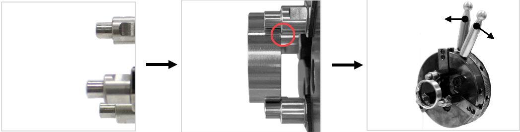
¶ How to secure a thin ring when marking the inside
When marking on thin rings, first, replace the finger chuck to 2mm with a finger chuck spanner. Then, insert the ring into the finger chuck. Last, fasten the ring with the finger chuck handle. To widen or tighten the gap of the finger chuck, use the finger chuck handle.
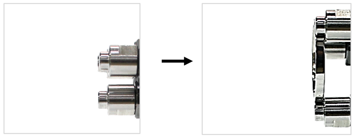
[Bangle]
¶ 7) Anti-curling Clamp
※Anti-curling clamp is sold separately.
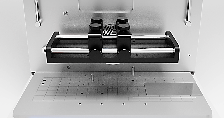
Anti-curling clamp is used for holding thin plates in place.
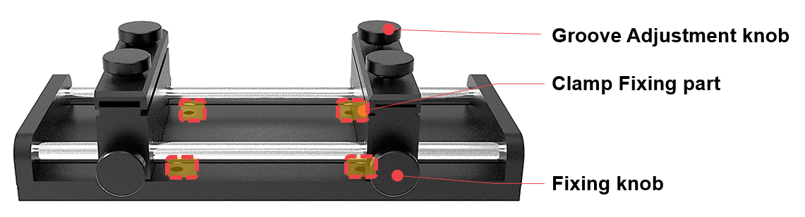
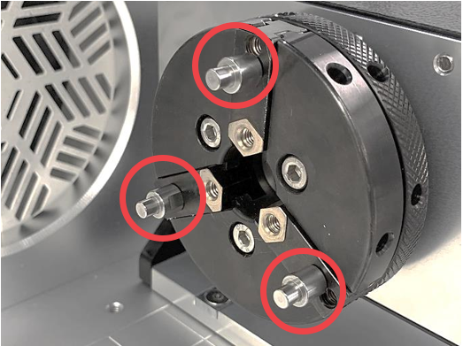
- Insert the clamp fixing pins (RP-0615) into the holes to secure the anti-curling clamp on the work area.
- Connect the anti-curling clamp to the pins attached to the work area.
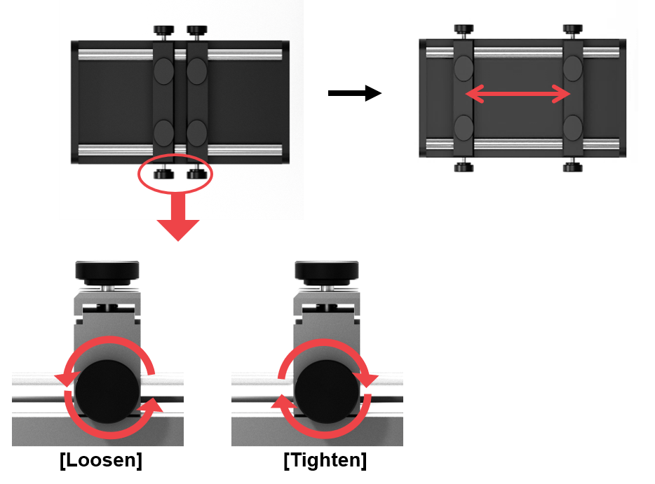
- Turn the fixing knob to widen the gap of the clamp.
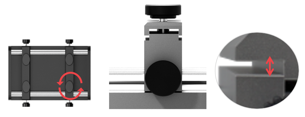
- Turn the groove adjustment knob to the left to loosen the groove of the clamp.
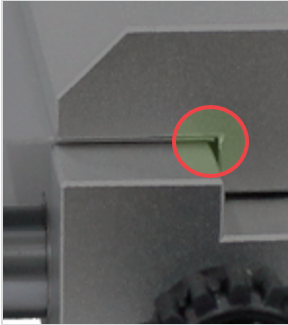
- Place and secure the material to mark. Turn the groove adjustment knob to the right to fasten the groove of the clamp.
¶ 8) Bangle Clamp
※Auto-tilt bangle clamp is sold separately.
| Anti-drop pin (6Ø) (18mm) |
|
1EA | To secure the bangle clamp and to prevent it from falling during operation. |
| Finger Chuck Handle (CP-31) |
|
2EA | Handle for the external adjustment knob. |
| Silicone Tube | 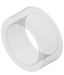 |
2EA | Non-slip Skin |
| Handle | 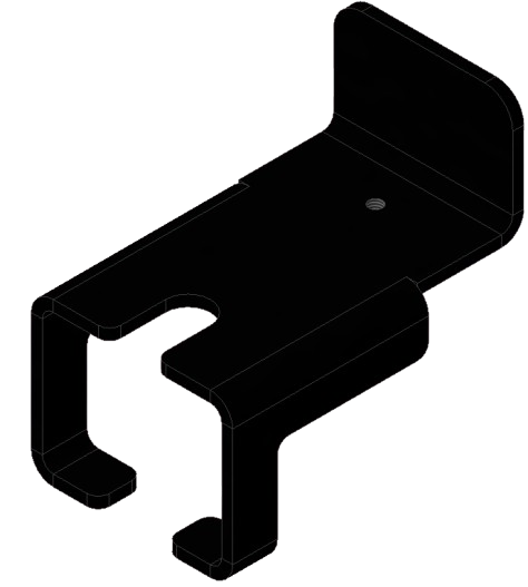 |
1EA | Handle for lifting fingers (used when attaching or detaching materials) |
| Auto-tilt bangle clamp (CL-19) |
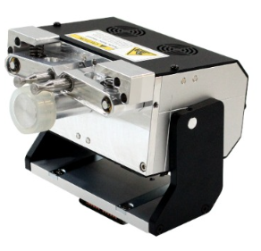 |
1EA | For holding ring materials in place.
※4mm chuck finger is included. |
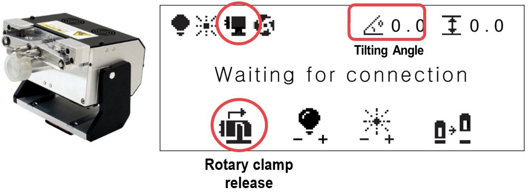
When using the bangle clamp auto tilting function, set the tilting origin to the 0 degree.
(See [Machine setting] -5. Rotary origin for further details)
¶ How to connect the bangle clamp
- Place the bangle clamp on the docking station and slide it to the left.
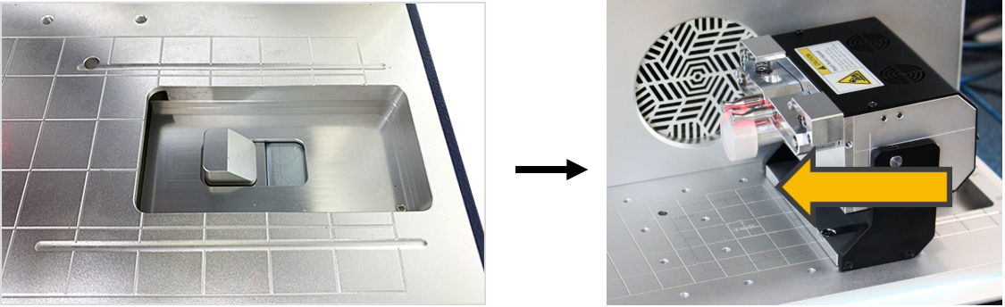
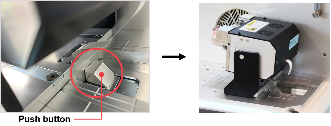
- Push the bangle clamp completely to the left until the push button fully lifts then beeps. Once the clamp is connected to machine, the machine will automatically recognize the device then it will begin to perform the initial operation.
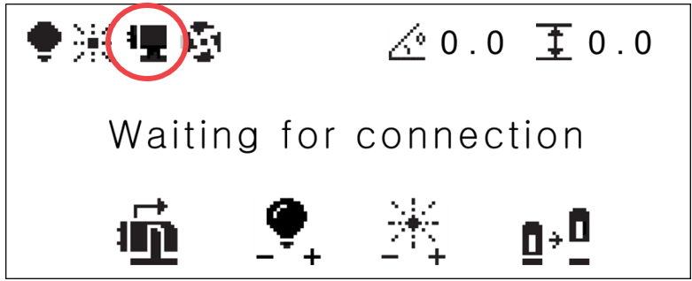
- A mounting icon will appear on the screen.
- Insert the anti-drop pin into the work area to secure the bangle clamp and to prevent it from falling during operation.
Anti-drop pin (6Ø) (18mm)
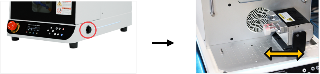
- Use the external adjustment knob (on the right side of the machine) to slightly adjust the position of the bangle clamp from left to right/right to left.
¶ How to disconnect the bangle clamp
- Press the bangle clamp release button to disconnect the bangle clamp.
- The bangle clamp will be tilted to 90 degrees. Follow the instruction that will appear on the screen.
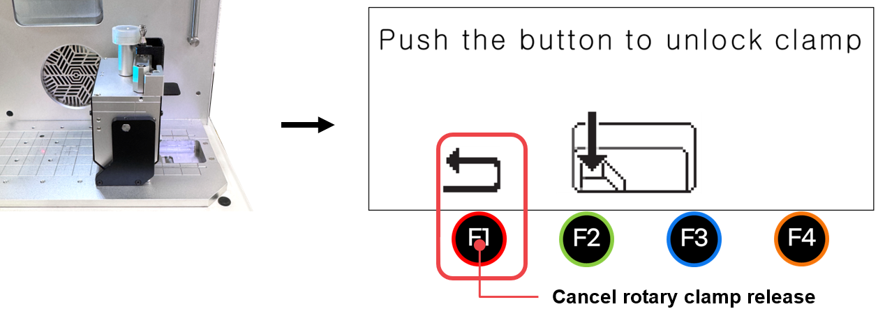
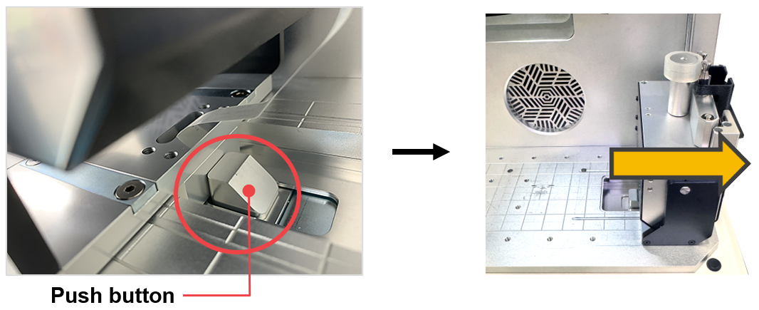
- Press the push button to release the bangle clamp then slide it to the right to put it aside.
¶ Fixing Method for Bangle Outer Engraving
| Handle | |
1EA | Handle for lifting fingers (used when attaching or detaching materials) |
- Use the handle or your hand to lift and hold the two fingers.
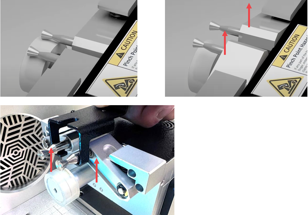
- Place the bangle so that its inner side touches the silicone tube and is positioned at the horizontal center. Then, lower the fingers you held up.
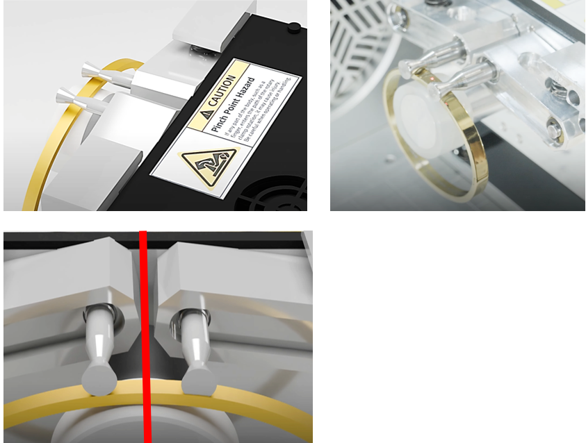
-
Use the ▲▼ (vertical direction) buttons on the keypad to rotate the bangle axis and adjust it to ensure the bangle rotates centrally.
※If it is bit aligned properly at the center, engraving may not be positioned as desired, and the material could slip out. -
After use, lift the two fingers again to remove the bangle.
¶ Fixing Method for Bangle Inner Engraving
- Use the handle or your hand to lift and hold the two fingers.
- Place the bangle so that its outer side touches the silicone tube and is positioned at the horizontal center. Then, Lower the fingers you held up.
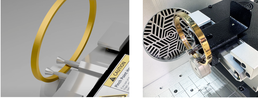
-
Use the ▲▼ (vertical direction) buttons on the keypad to rotate the bangle axis and adjust it to ensure the bangle rotates centrally.
※If it is bit aligned properly at the center, engraving may not be positioned as desired, and the material could slip out. -
After use, lift the two fingers again to remove the bangle.
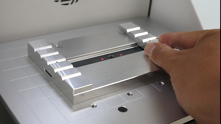
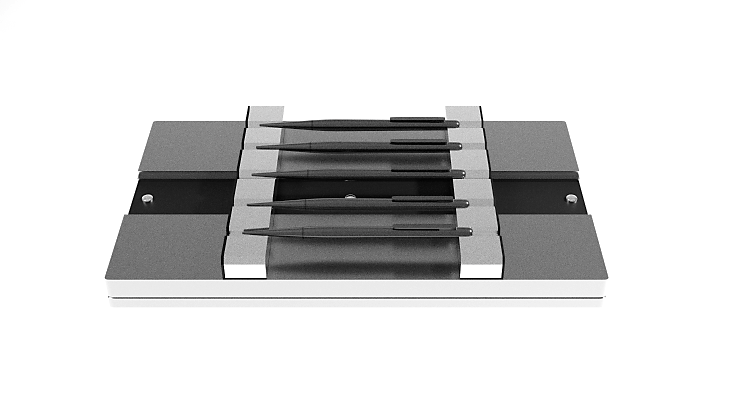
¶ 9) Pen Clamp
※The pen clamp is sold separately.
| Pen Clamp (LMC-171) |
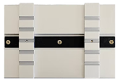 |
1SET | Clamp for securing the pen |
| Horizontal Adjustment Bar |
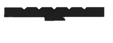 |
2EA | Auxiliary jig for leveling the pen |
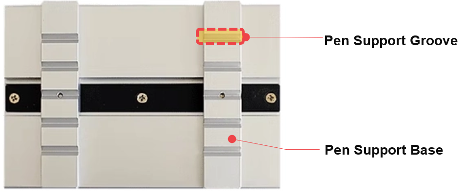
- Insert the clamp fixing pins (RP-0615) into the holes to secure the pen clamp.
- Attach the pen clamp to the clamp fixing pins.
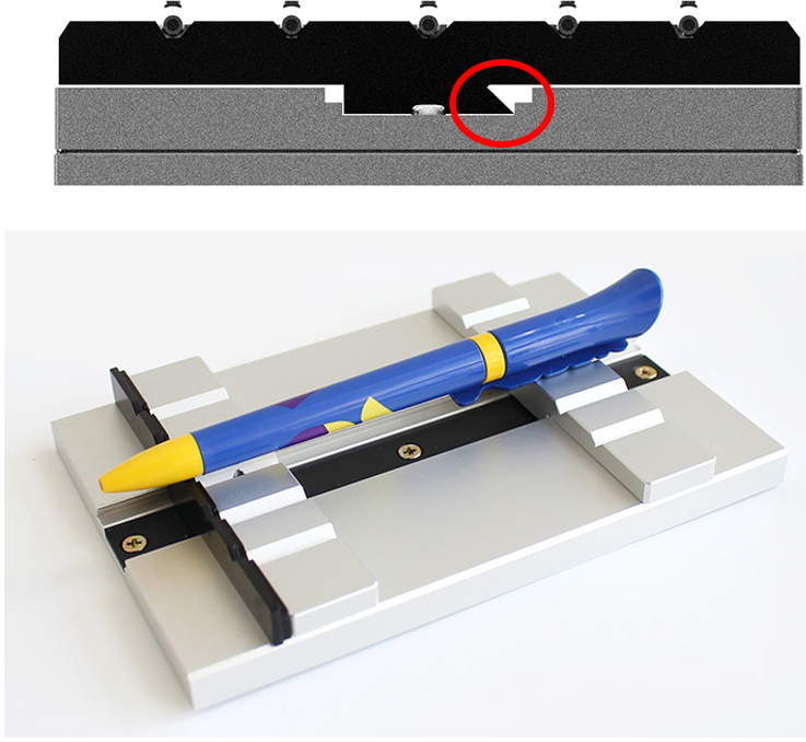
- To ensure the pen is positioned horizontally, adjust the pen support base left or right so that the pen rests on the support groove.
- If it is difficult to level the pen using only the pen support base, insert the horizontal adjustment bar on either side to level the pen. Install the horizontal adjustment bar with the red contact surface facing either the front or rear of the machine.
¶ 3. Keypad
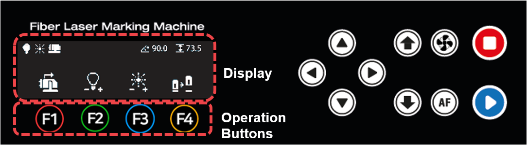
| Display | Status display | ||
    Operation Buttons |
Activate the operations intended to perform | ||
 |
Direction Key (X,Y/Z/A) |
Marking area adjustment  (X) Moves tilting angle (X) Moves tilting angle  (Y) Moves A axis (Y) Moves A axis |
|
  |
Direction Key (Z) | Moves Z axis up and down | |
 |
Blower ON/OFF | Blower power button • Automatic control: The device starts automatically once the marking operation begins and stops automatically once the marking operation is completed. • Manual operation: Automatic control is deactivated if the device is manually switched on. Once the marking operation is completed, the device should be manually turned off. |
|
 |
Auto Focus | • AUTO FOCUS: Short press to auto-focus the laser to the material height. *Auto focus is activated once the program is connected. *Only for flat marking *Auto focus maximum measurement height: 55mm *Auto focus cannot be used on materials that would not reflect red laser like acrylic, glass, red anodized aluminum, or chrome-plated pendants. • MENU: Long press to enter menu mode. 1: Product Info 2: Status LED Brightness 3: Reset Memory Long press and hold  button (for more than 2 seconds) until it beeps to run the menu. button (for more than 2 seconds) until it beeps to run the menu. |
|
|
Start | Start marking button • Start marking: Long-press (for 2 seconds) the button to start marking.• Repeat marking: Press the button to finish marking, then double-press (tap twice) the button to repeat marking. |
|
 |
Stop | Stops/cancels marking | |
¶ 4. Display
The display shows the status, functions, mode, and check messages. Icons are displayed differently depending on the selected function. The four buttons at the bottom represent different functions and each function vary depending on the selected mode.
¶ 1) Standby Mode
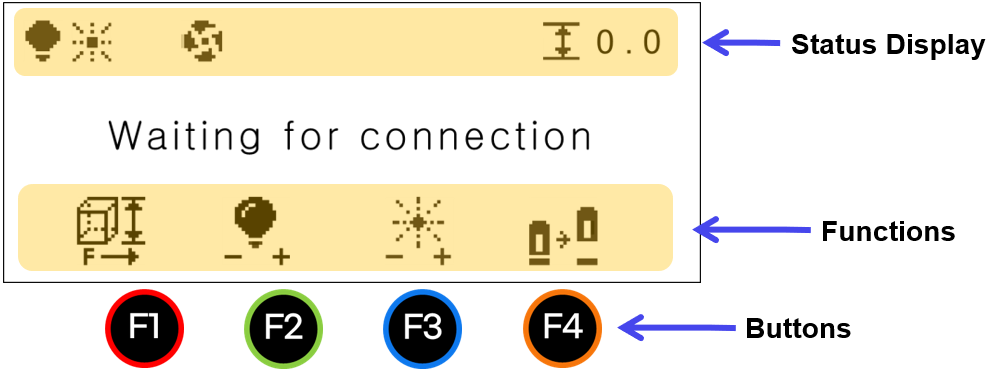
| Status | ||
|---|---|---|
 |
LED Light | Brightness levels |
 |
Focus Pointer | Brightness levels |
 |
Dust Collector | Dust collector ON/OFF: Icon does not appear when OFF |
 |
Z-axis Position | Z-axis Position: Material height |
| Functions | ||
|---|---|---|
 |
Height | • Move to a preset height: Short-press the button to move the laser focus to a preset height. • Save preset values: Long-press the button to save laser focus preset values. |
 |
LED Light | Brightness levels There are 4 levels of brightness control. Each time the button is pressed, the level changes as well as the level cycles. 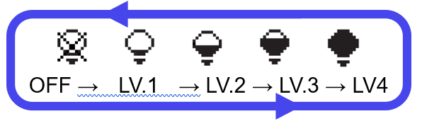 |
 |
Focus Pointer | Brightness levels There are 4 levels of brightness control. Each time the button is pressed, the level changes as well as the level cycles. 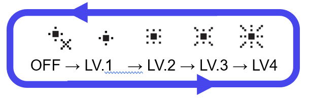 |
 |
Cover | Opens/closes the front cover. |
¶ 2) Marking Mode
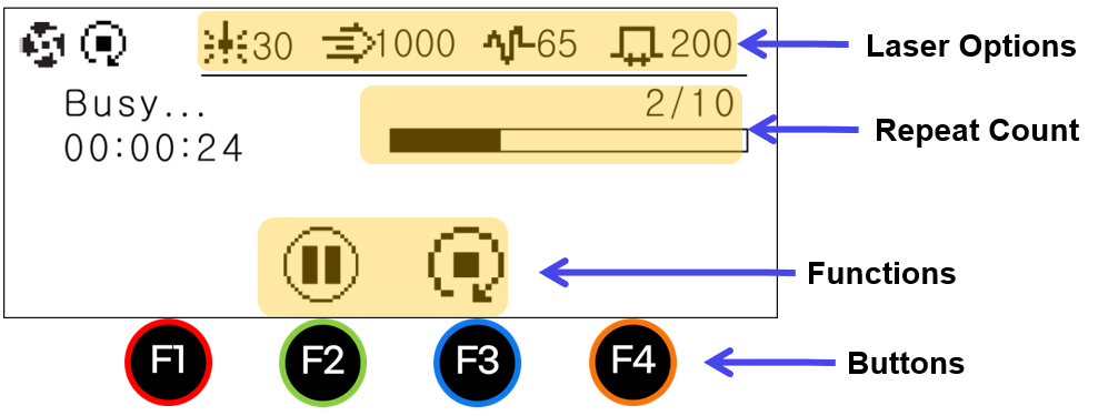
| Status Display |  |
Stop after current operation | The marking does not stop immediately; it stops after completing the marking in progress. |
| Laser Options |  |
Power | Displays set laser power value |
 |
Speed | Displays set laser speed value | |
 |
Frequency | Displays set laser frequency value | |
 |
Pulse width | Displays set laser pulse width value | |
| Time left | The remaining time until marking completion is displayed. ※Calculate the time required for the 1st cycle. |
||
| Repeat Count | When setting a repeat count, the number of repeats is displayed. (Example: 2/10 → performing 2 times out of a total 10 markings) |
||
| Functions |  |
Pause | Pause the operation in progress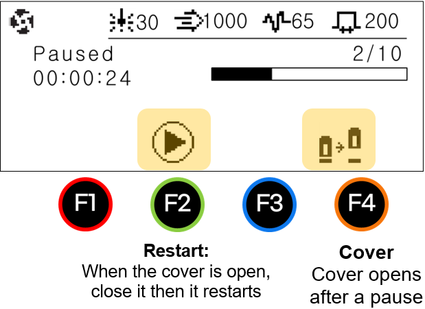 |
|
Stop after current operation | End repeated marking in progress. The marking does not stop immediately; it stops after completing the marking in progress. | |
¶ 3) Rotary Mode
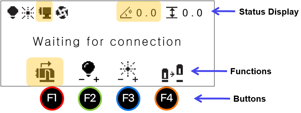
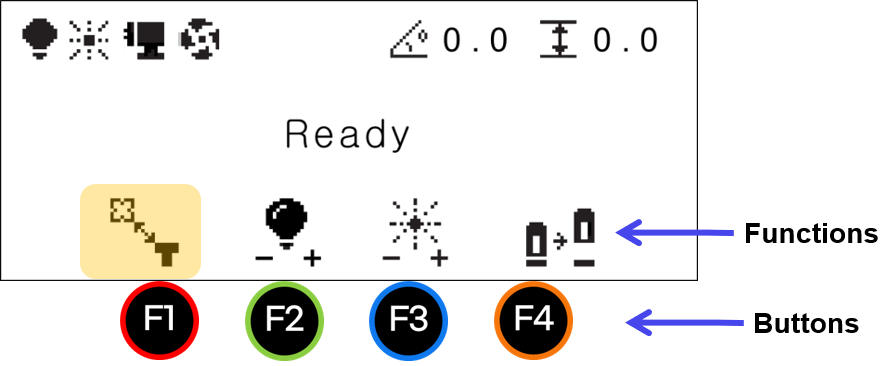

| Status Display |  |
Rotary Clamp | Displays rotary clamp mounting |
 |
Angle | Displays tilting angle | |
| Functions |  |
Rotary Clamp | Rotary clamp release button |
 |
X-axis/Tilting | When checking the rotary clamp marking area • Moves when tilting axis is active. • When the X-axis is activated, the position moves in the X-axis direction. |
¶ 4) Rotary Scan Mode
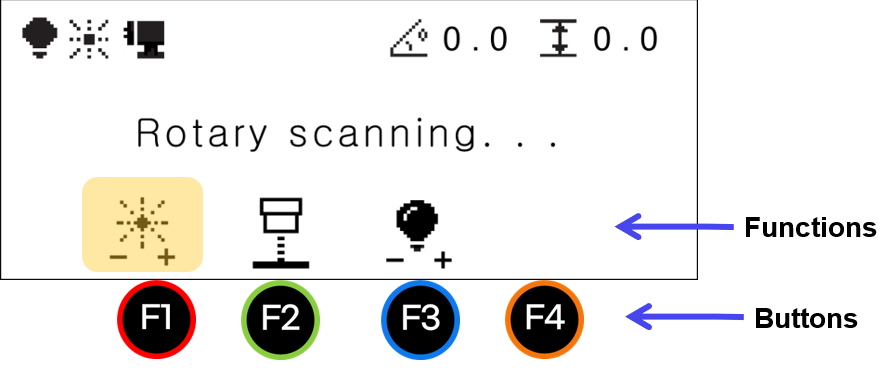
|
Focus Pointer | Brightness levels There are 4 levels of brightness control. Each time the button is pressed, the level changes as well as the level cycles. |
 |
Head Pointer ON/OFF | Head Pointer ON/OFF
· What is the Head Pointer? |
|
LED Light | Brightness levels There are 4 levels of brightness control. Each time the button is pressed, the level changes as well as the level cycles. |
| F4 | No Function | No Function |
¶ 5. Status Indicator
The status indicator is placed at the bottom left side and bottom right side of the machine. It is used to indicate the status of the device.
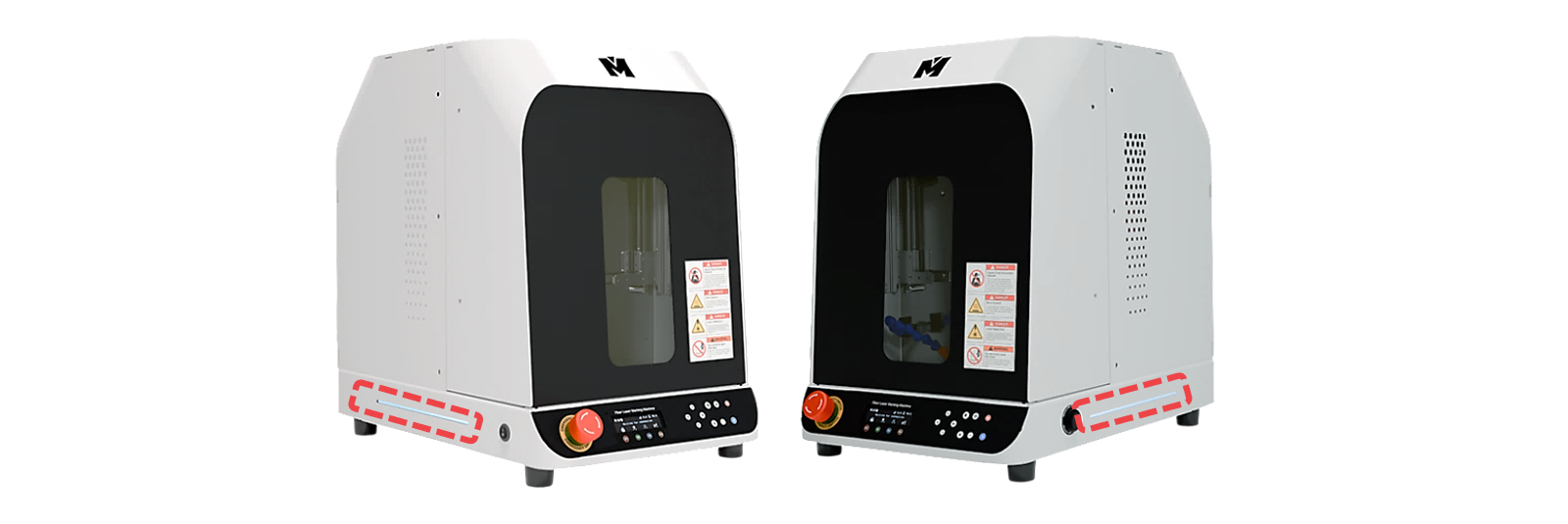
The machine displays flashing or blinking lights to show its current status. The lights displayed indicate the following status:
| Status | Blinking Interval |
| Computer connecting |  |
| Waiting |  |
| Operating | |
| Notification |  |
| Error |  |
Long-press button (for 2 seconds) to enter menu mode.
MENU:
1: Product Info
2: Status LED Brightness
3: Reset Memory
Press and hold button (for more than 2 seconds) until it beeps to run the menu.
Use 
 (Direction X) buttons to adjust the brightness level.

¶ 6. Air assist nozzle
※ Air assist nozzle is sold separately.
※ The air pump and hose are not included.
● Ensure that the air assist nozzle is aimed toward the central intake port.
● Set the air or gas flow rate and pressure so that they do not exceed the dust collector's suction capacity. Excessive airflow may cause dust to scatter inside the chamber, potentially resulting in equipment malfunction.
● Before operation, use the flow control lever to adjust the airflow to a level suitable for the application.
● When using an air compressor, be sure to install a moisture filter (air filter/water separator) to prevent moisture from entering the system. Moisture-contaminated air may reduce cutting quality and cause equipment malfunction.
● Verify that the nozzle tip does not interfere with the laser beam path or the workpiece.
● Excessive air pressure may cause the workpiece to vibrate or small parts to shift. Use an appropriate air pressure for the application.
[Installation Instructions]
-
Turn on the machine and open the cover.
-
Screw the air assist nozzle onto the fitting at the lower-left front of the machine and tighten it securely.
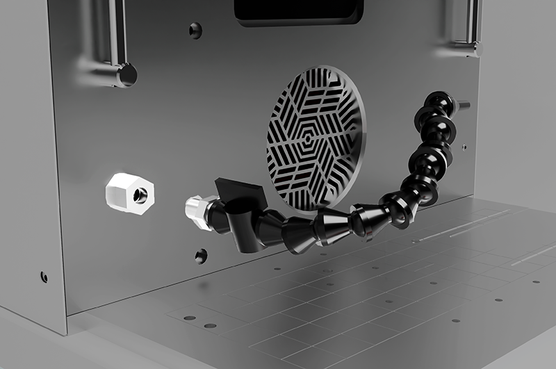
- Connect the hose from the air pump to the air assist hose inlet located on the rear panel.
A Ø6 mm (0.24 in) urethane hose is recommended.
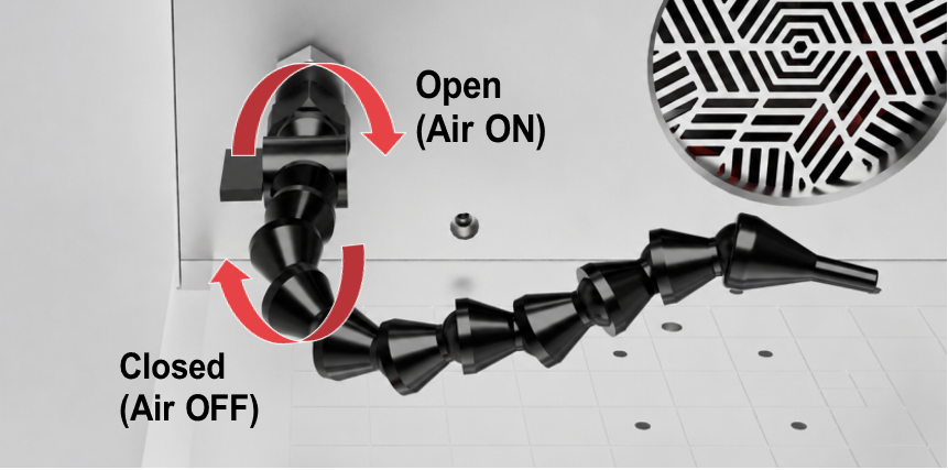
- Turn on the air pump, then rotate the valve on the air assist nozzle clockwise until the valve lever is aligned with the nozzle direction. The valve is now open. Adjust the airflow by varying the valve opening. When the Air Assist is not in use, rotate the valve counterclockwise (to the left) to close it.