¶ Contents
- 1. Toolbar
- 2. Text Object Property
- 3. Rotation tool property
- 4. How to engrave for each toolpath
- 5. Create toolpath
- 6. Laser option
- 7. Data output
- 8. Auto focus
¶ Before Using the Program
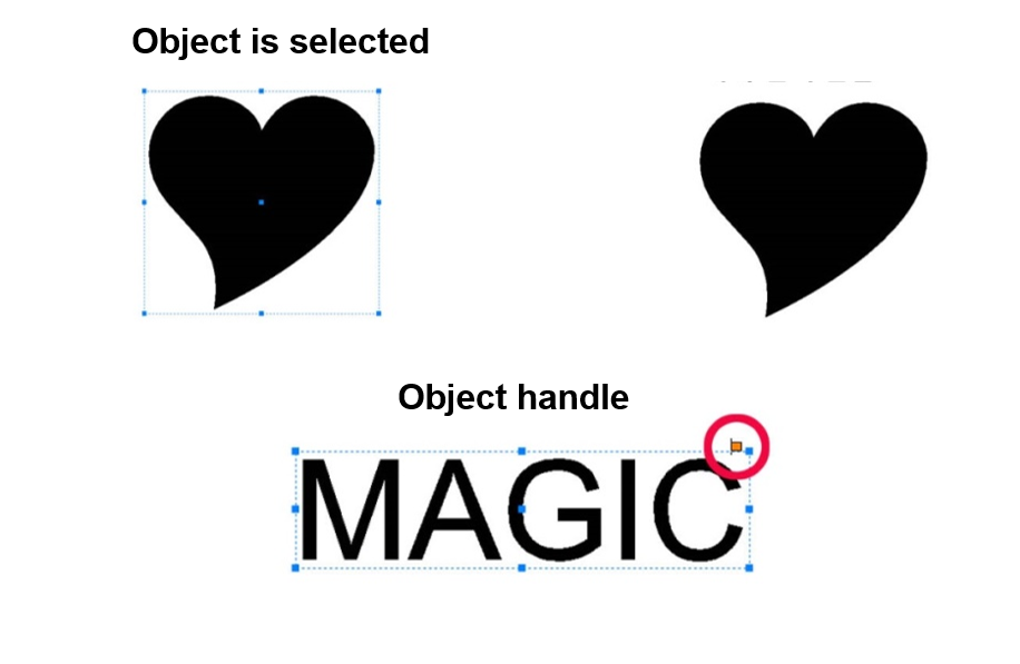
The property of the object (i.e., size, shape, position, etc.) can be changed or modified when the object is selected.
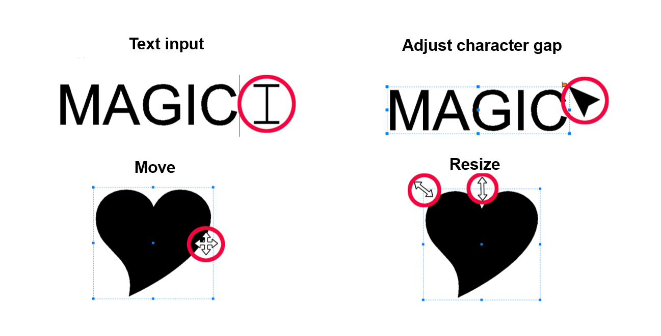
The mouse cursor display changes depending on the function (i.e., text input, resize, select, etc.).
¶ Program Usage Description
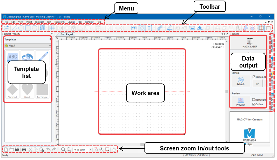
Shown below is the window that will appear once the program starts running. Icons displayed on the window may vary depending on the selected mode.
The name of each category is as follows:
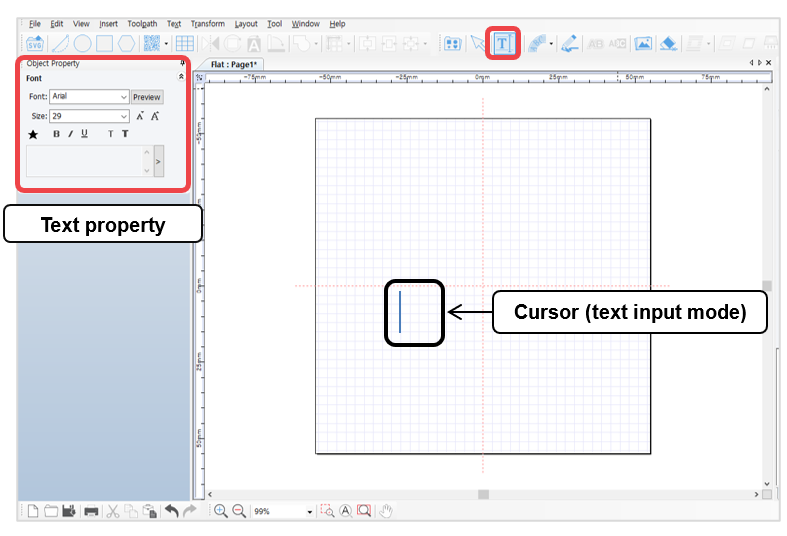
Click [Text Input] button on the upper center of your screen or double-click on the composition area to input text.
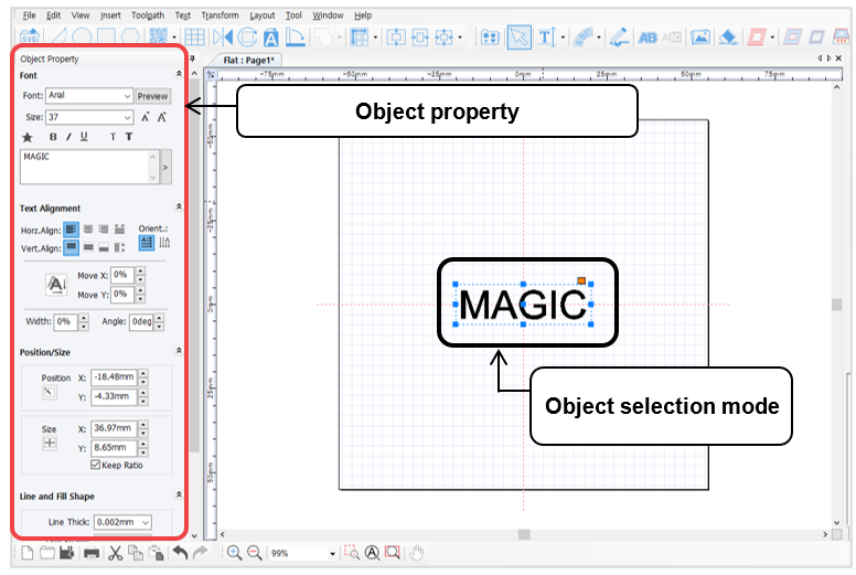
After entering the text, use [Selection] button with your mouse or right-click the text on the composition area to switch to selection mode.
To switch to text input mode, double-click on the selection mode.
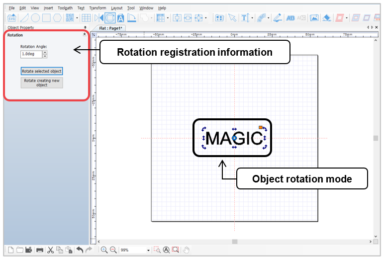
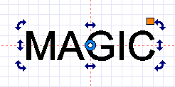
To activate object rotation mode, double-click the text while in selection mode.

¶ 1) Toolbar
¶ (1) Alignment Tools
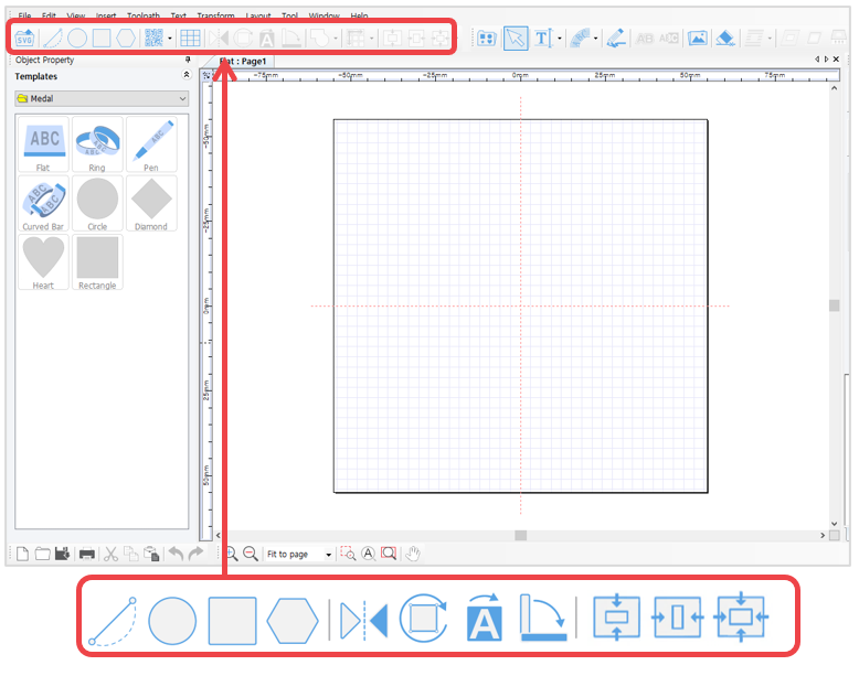
 [Line/Curve]
 |
Click a certain point then hold your mouse and drag to make a dot line appear. Designate the distance then right-click to create a straight line. Then, press “Ctrl” key on the keyboard and move the mouse to create a horizontal line or a vertical line. |
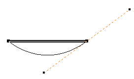 |
Click a certain point and designate a distance. Hold your mouse and drag to make a curve appear. Right-click to create a curve. |
 [Circle/Oval/Pie]
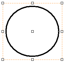 |
Click the work area then hold your mouse and drag to designate the size of a circle. Press “Shift” key on the keyboard then drag your mouse to create a perfect circle. |
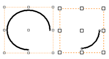 |
Click "Art" button on the circle object property window to convert to arc. The start/end of an angle of an arc can be assigned, or adjusted by dragging the start/end with the mouse. Click "CW/CCW" button to create a reversed arc image. |
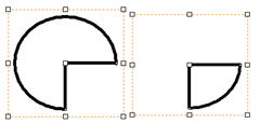 |
Click “Pie” button on the circle object property window to convert to pie (a filled arc). The start/end of an angle of a pie can be assigned, or adjusted by dragging the start/end with the mouse. Click "CW/CCW" button to create a reversed pie image. |
 [Rectangle]
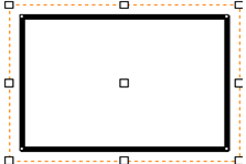 |
Click the work area then hold your mouse and drag to designate the size of a rectangle. Press “Shift” key on the keyboard then drag your mouse to create a square. |
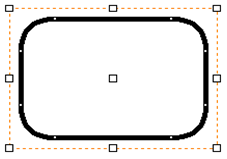 |
The curvature of each edge can be assigned on the rectangle object property window. Or, by dragging the edges of the rectangle with the mouse, the edges convert into round corners. |
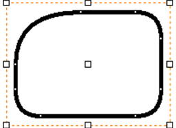 |
Click “Independant Corner” button on the rectangle object property window to adjust the curvature of each corner individually. |
 [Polygon]
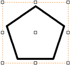 |
Click the work area then hold your mouse and drag to designate the size of a polygon. The number of vertices can be assigned on the polygon object property window. |
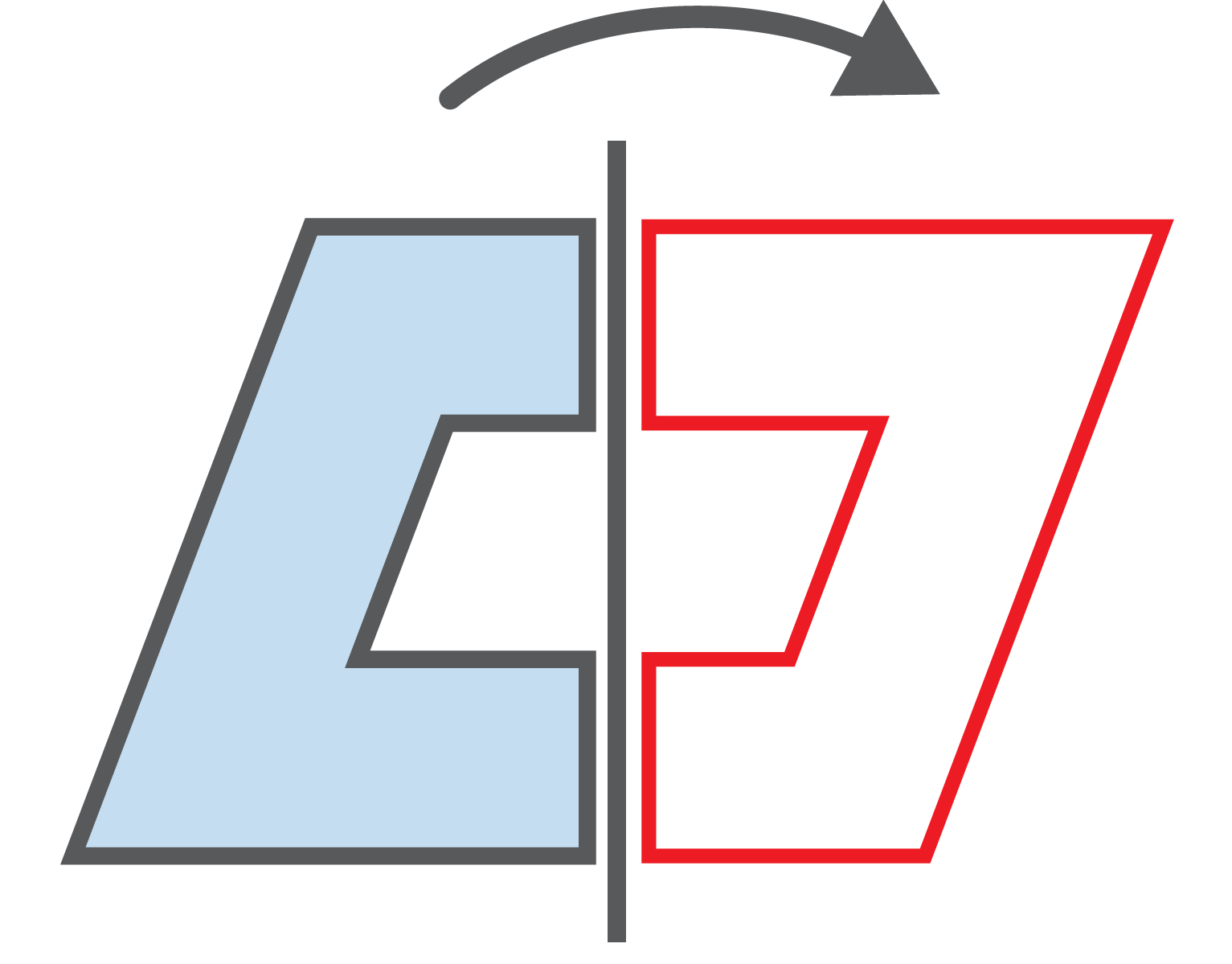
 [Mirror] Produces mirrored image.

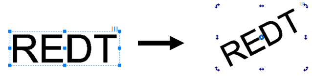
 [Rotation] Double-click to select rotation then hold your mouse and drag to rotate the image.
 [Invert color] Inverts the color of the image.

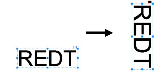
 [90˚CW] Rotates the image by 90˚.
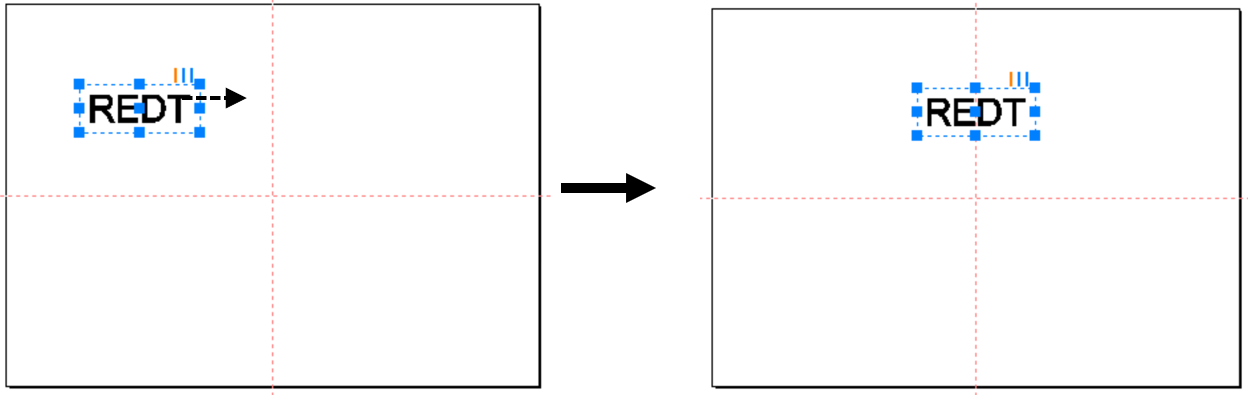
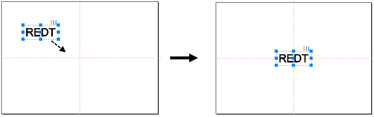
 [Horizontal center in page]
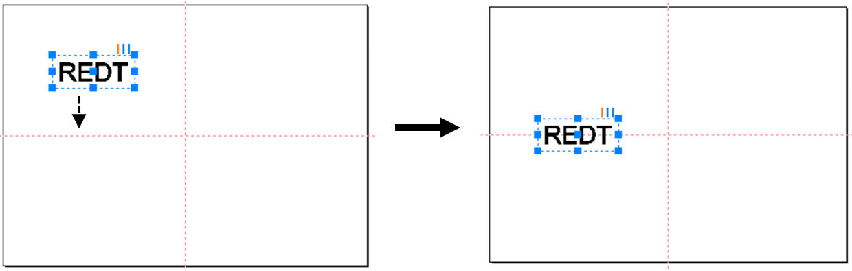
 [Vertical center in page]
 [Center in page]
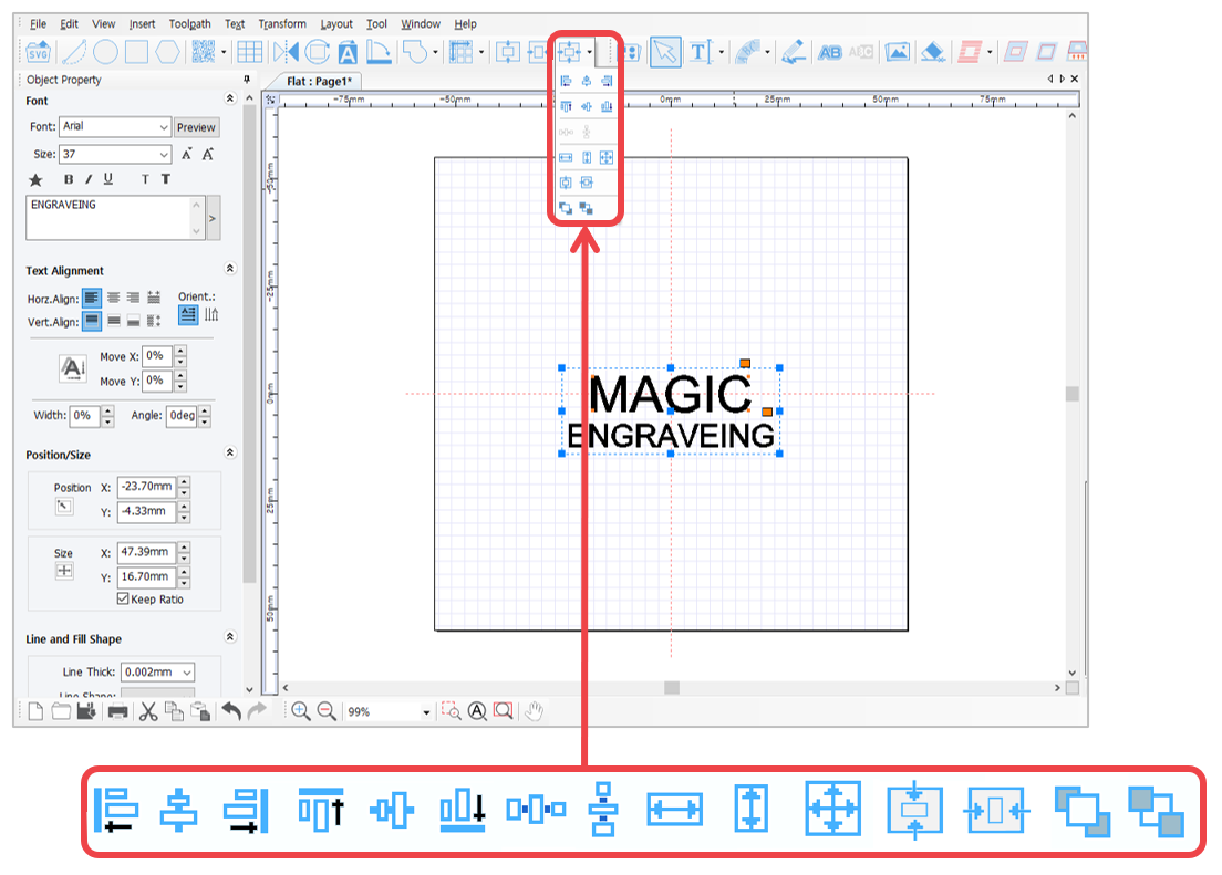
¶ (2) Alignment Options
| Alignment |  |
Align to the left of base object |
 |
Align to the center of base object | |
 |
Align to the right of base object | |
 |
Align to the top of base object | |
 |
Align to the center of base object | |
 |
Align to the bottom of base object | |
| Adjust horizontal gap |  |
Align horizontal gap between objects evenly |
| Adjust vertical gap |  |
Align vertical gap between objects evenly |
| Same size |  |
Make same width |
 |
Make same height | |
 |
Make same size | |
| Alignment |  |
Horizontal center in page |
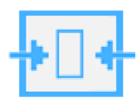 |
Vertical center in page | |
| Order |  |
Bring to front |
 |
Send to back |
¶ (3) Object tools
 |
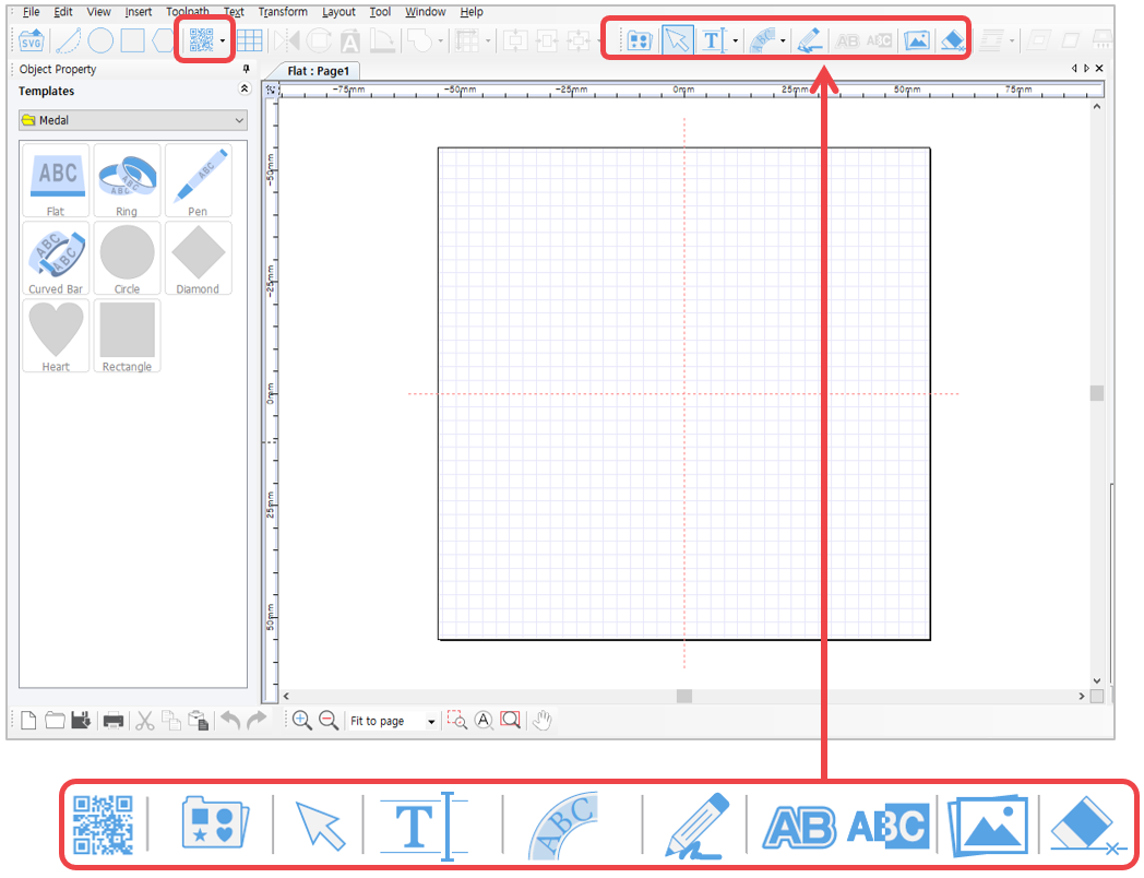
[Barcode] | Create a barcode object.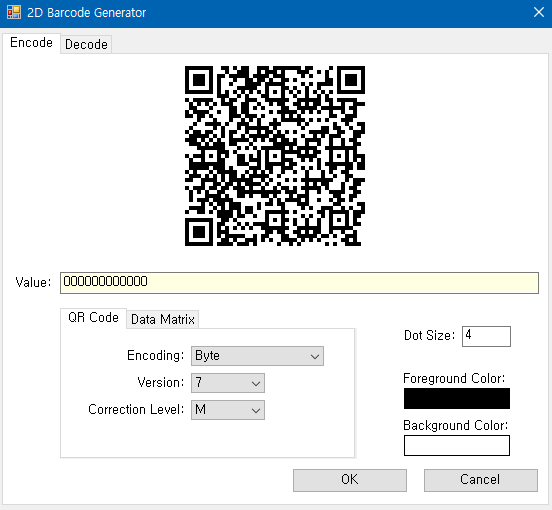 |
 |
[Design sample] | Import design sample or save current object as design sample.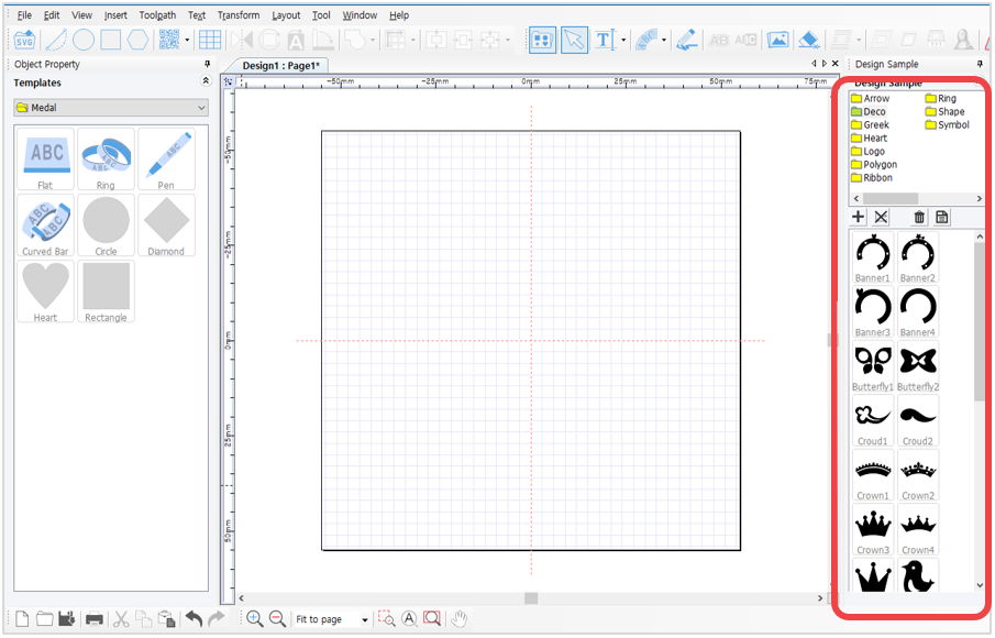  What is a Design Sample? Design sample is the object saved in the design sample library. Design samples can be easily and quickly imported from the design sample library and edited freely. |
 |
[Selection] | Use selection mode to modify the object’s property or adjust its size and position. To use, click the object created in the work area then adjust its property. To input text, right-click. 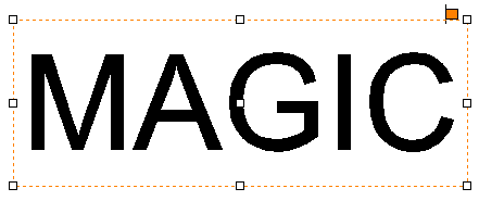 [Object selected] [Object selected]  [No object selected] [No object selected] |
 |
[Text input] | To input text, click “Text input” button then click the object in the work area or, simply double-click to enter text. To modify the object’s font style and size, click “Text input” button then hold and drag the character/s with the mouse.  Click LMB button to create a text box. Then hold and drag the mouse to adjust the size of the text box. The size of the text box limits the number of character input.  A blinking cursor display indicates ‘enter text.’  Or, go to [Menu → Insert → Text box]. 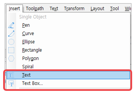 |
 |
[Circular text] | Create text objects along a circle.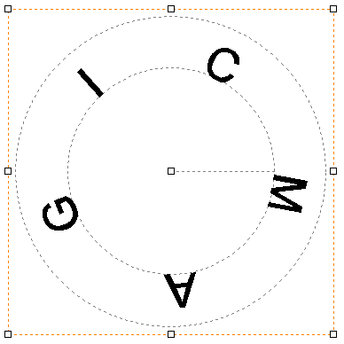 |
 |
[Drawing pen] | Hold and drag the mouse to draw character/s to create an object with the use of drawing pen. The drawing line’s thickness can be adjusted in the drawing object property window.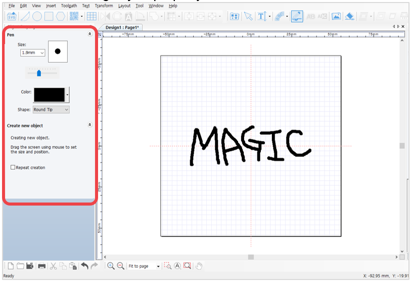 |
 |
[Outline stroke of object] | Apply outline stroke to the object.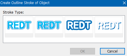 |
 |
[Auto Inverts Color] | The color of one object auto inverts to opposite color to contrast the other object’s color when overlapped. Click [Auto Inverts Color] button then select the object to be placed over the target object. Upon pacing the selected object over the target object, the selected object auto inverts to an opposite color.  For texts, click the [Auto Unverts Color] button then drag the selected text and place it over the target object. 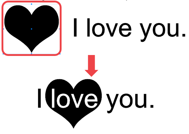  If the color is not inverted, go to [Layout menu → Order → Top Most] then place the selected object over the target object. |
 |
[Image] | Import image (e.g., bmp, jpeg, gif, png … etc.).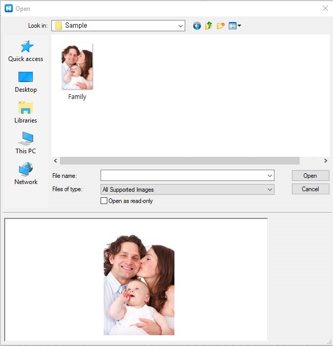 |
 |
[Line eraser] | Erase the line of a created object. Click the object to be erased then hold and move the mouse over the line to erase. (Take note that some objects may not be erased with the Line eraser tool).  |
¶ (4) Toolpath
※Please refer to [4. How to engrave for each toolpath] for details.
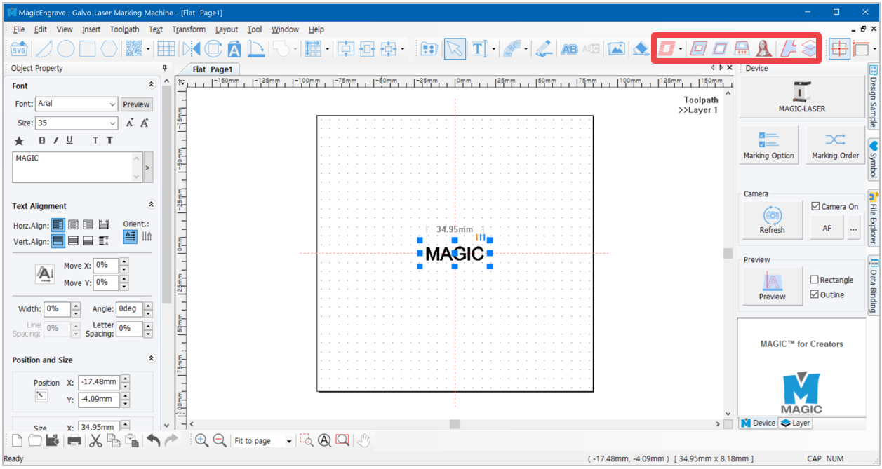
What is a Toolpath?
Toolpath is a path where the tool passes by for marking.
Toolpath is usually displayed in red color and the marking tool moves along the path as it engraves.
¶ (5) Origin point setting tools
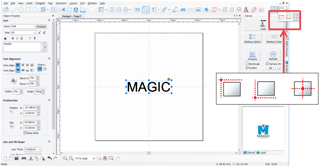
 [Left top origin point]
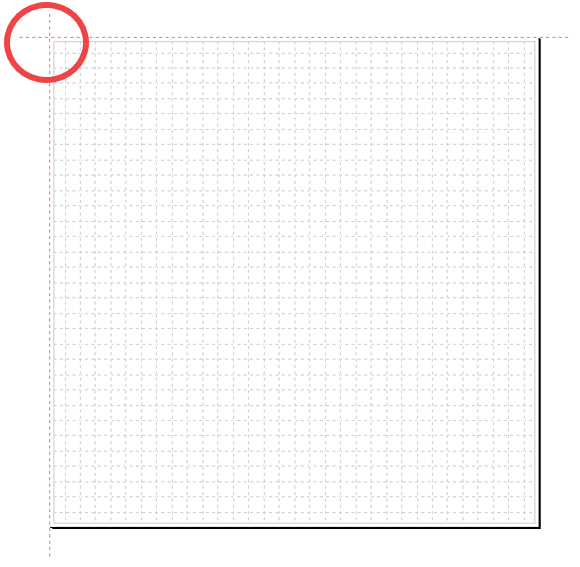
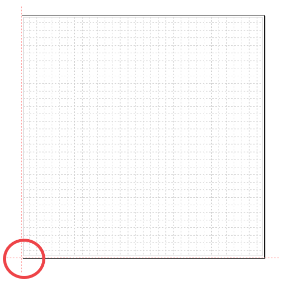
 [Left bottom origin point]
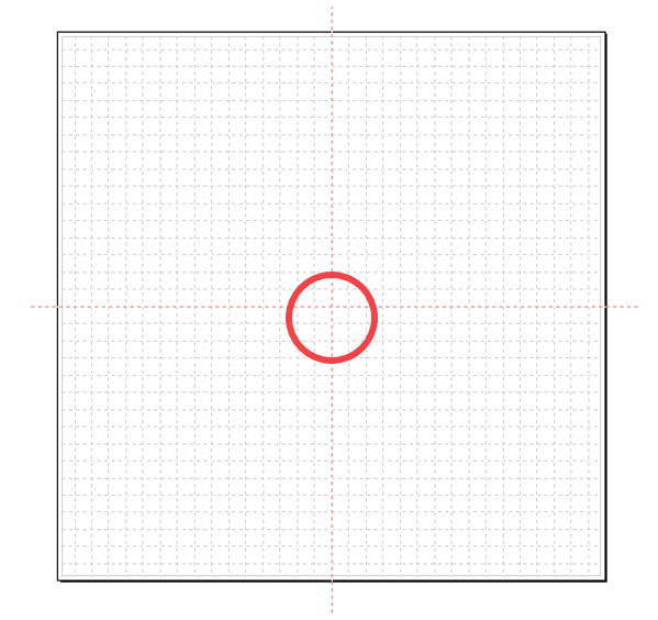
 [Center origin point]
¶ (6) Basic tools
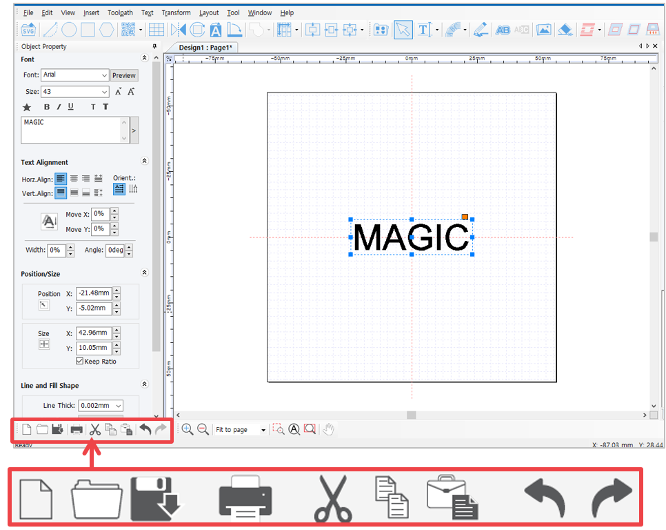
 |
[New document] | Open a new page. 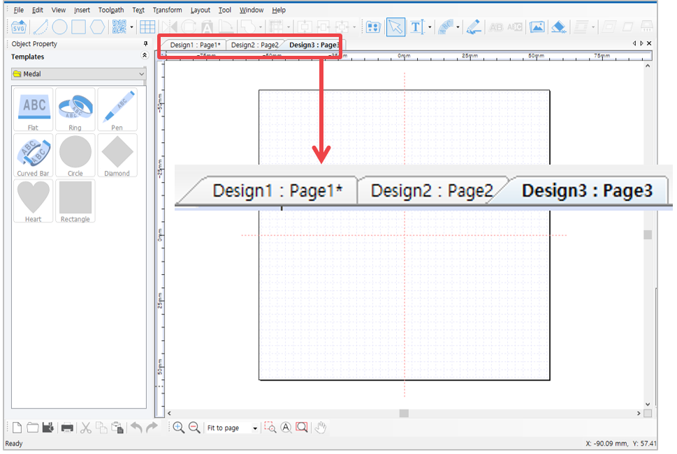 |
 |
[Open] | Open a file in “*.dgn” file format. Select a file on the “Open” window and click [Open] button. |
 |
[Save document] | Save the design created on program as “*.dgn” file format. Choose the location (folder) in which the file will be saved then enter the file name before clicking [Save document] button. |
 |
[Print] | Print the design created on program. |
 |
[Cut] | Cut the selected object. Click [cut] button on the menu or press Ctrl+X on the keyboard. 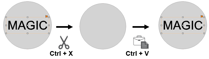 |
 |
[Copy] | Copy the selected object. Click [Copy] on the menu or press Ctrl+C on the keyboard.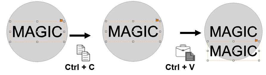 |
 |
[Duplicate Horizontally or Vertically] | To multi-copy the same object at once.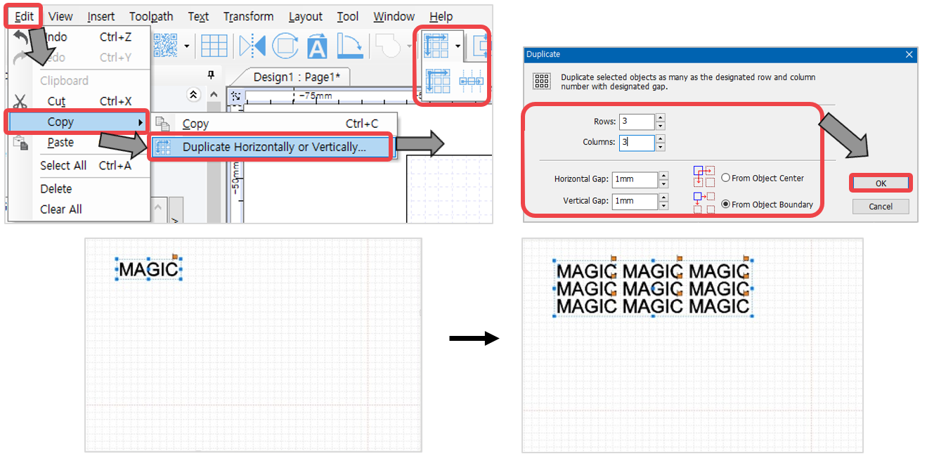 |
 |
[Paste] | Paste the cut or copied object. Click [Paste] button on the menu or press [Ctrl+V] on the keyboard. |
 |
[Undo / Redo] | Undo: To reverse the action recently done. Redo: To restore the action that was previously done. **Go to [Menu] → [Tool] → [Option] → [General] to adjust the number of undo action. 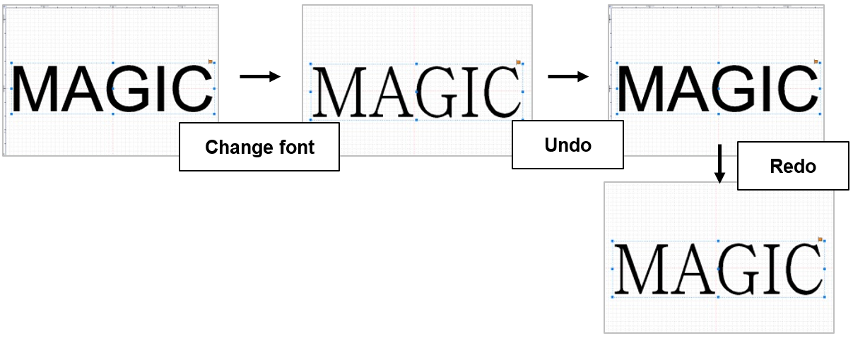 |
¶ (7) Screen zoom in/out/move tools
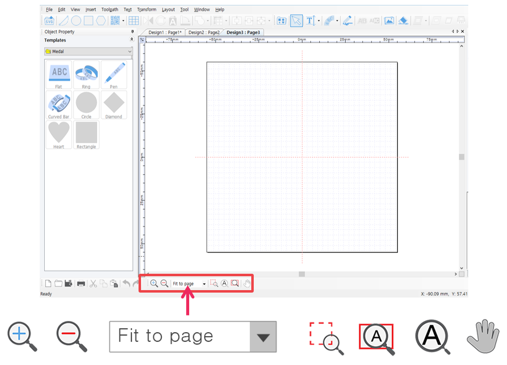
 |
[Zoom in] | The screen appears much larger and nearer.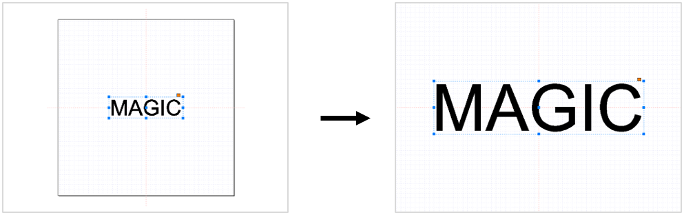 |
 |
[Zoom out] | The screen appears much smaller and farther.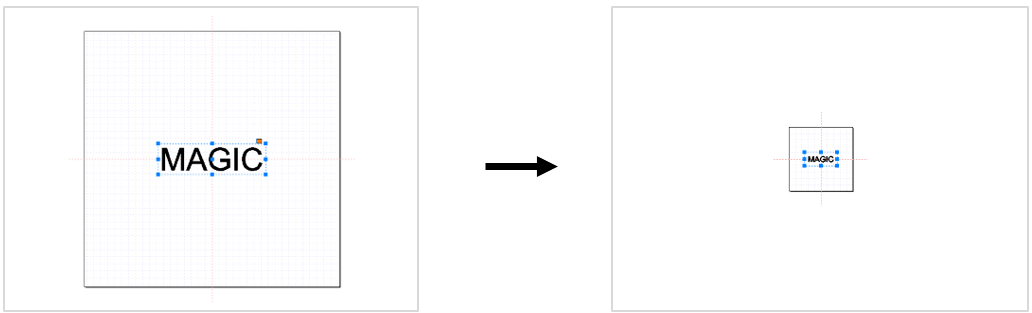 |
 |
[Zoom in/out ratio] | Select the desired screen ratio. The size of the screen will appear base on the selected ratio.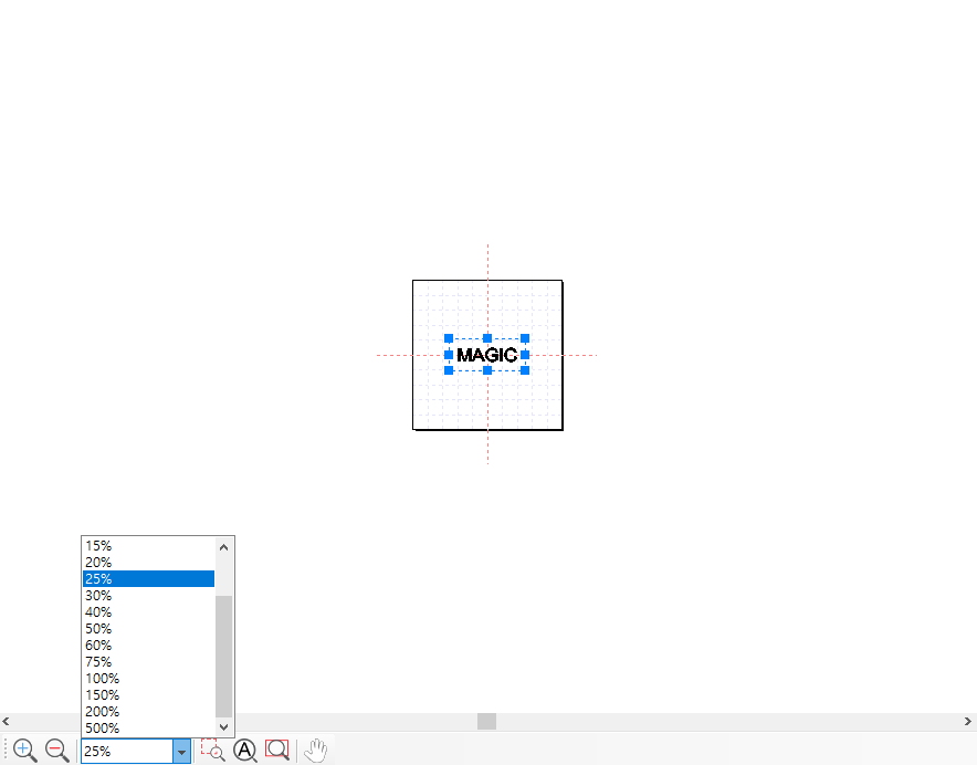 |
 |
[Magnifier] | Select a certain spot on the object then hold and drag the mouse to enlarge it.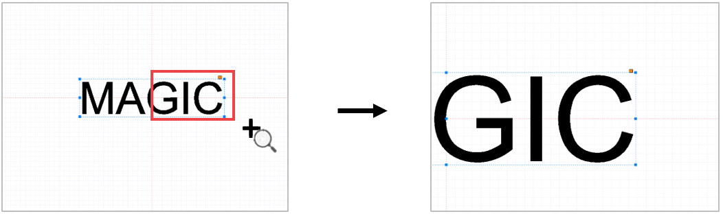 |
 |
[Fit to object] | Enlarge the object to fill in the screen.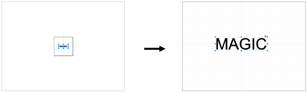 |
 |
[Fit to page] | Adjust the page size to see the whole work area.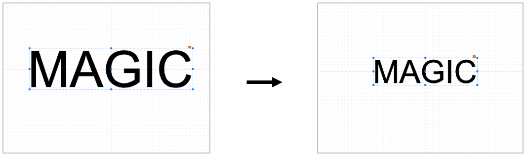 |
 |
[Panning] | Drag the screen with the mouse to move it.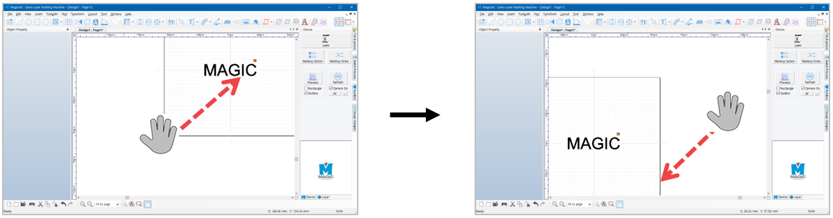 |
¶ 2) Text Object Property
Select the text object to see its property. The property of the object will appear on the left side of the screen.
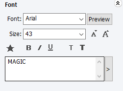
 [Font]
Designate font. Click “Preview” button or the arrow beside it to designate font.
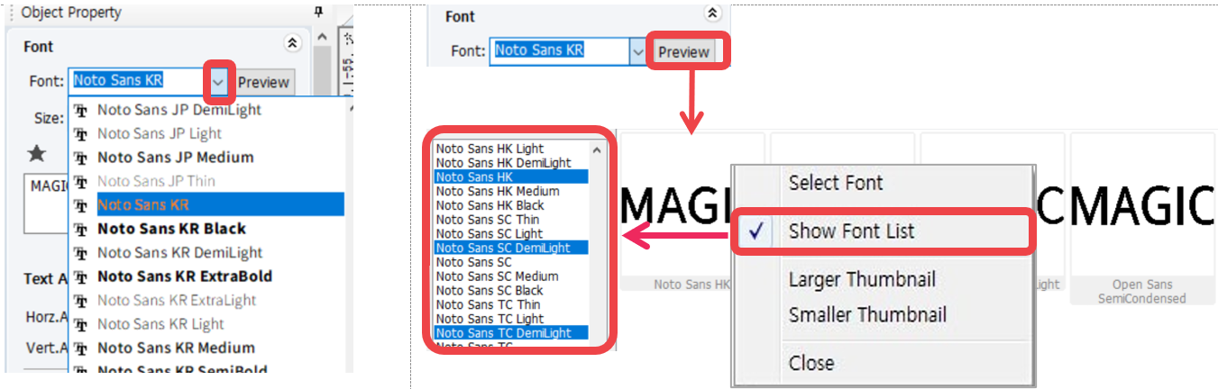
*Right-click the font preview window to see menu. Click “Show Font List” then designate the fonts to be shown in preview.
 [Size]
Adjust the size of the selected text. Click [Size] button to adjust the size of the font or the arrow beside it.
 [Bold]
Change text style to bold.

 [Italic]
Change the text style to italic.

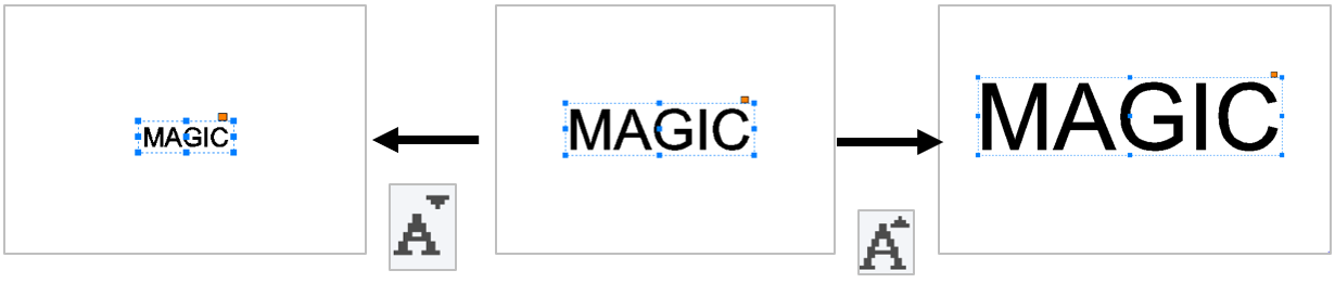
 [Reduce or increase font weight by one level]
Adjust the weight of font.

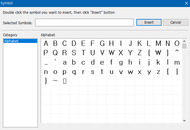
 [Symbol]
Insert symbols.
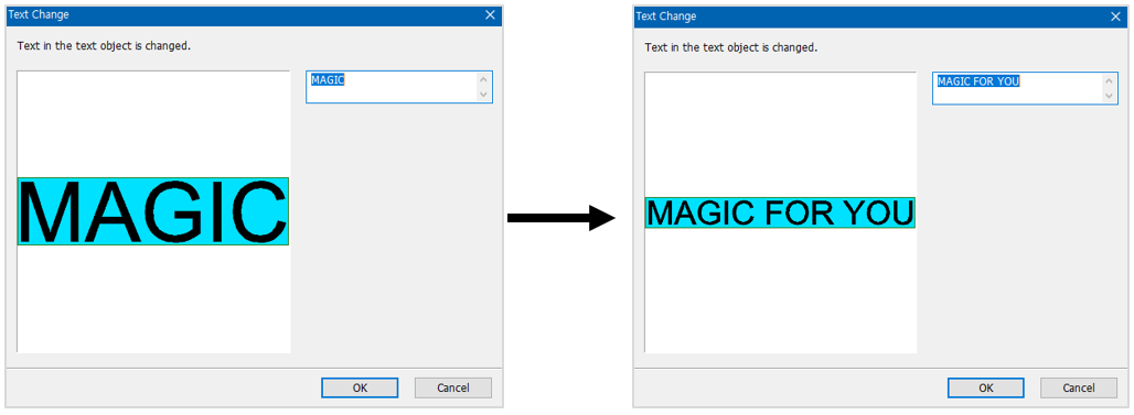
 [Text change]
Modify the entered text. Edit the text on the text field or click button to add long texts.
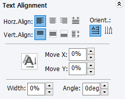 [Text Alignment]
 [Align to left] [Align to left] |
Align characters to the left in the text box.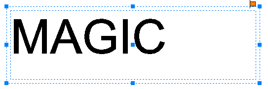 |
 [Align to center] [Align to center] |
Align characters to the horizontal center in the text box.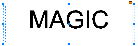 |
 [Align to right] [Align to right] |
Align characters to the right in the text box.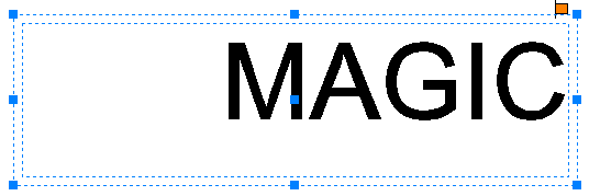 |
 [Both] [Both] |
Align characters evenly to both sides in the text box.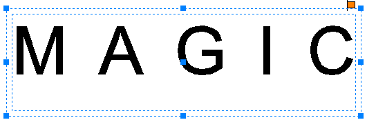 |
 [Align to top] [Align to top] |
Align characters to the top in the text box.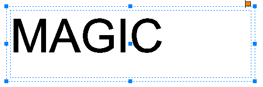 |
 [Align to center] [Align to center] |
Align characters to the vertical center in the text box.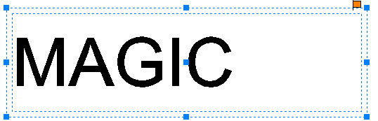 |
 [Align to bottom] [Align to bottom] |
Align characters to the bottom in the text box.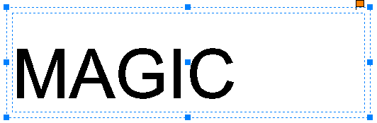 |
 [Horizontal text] [Horizontal text] |
Arrange characters horizontally.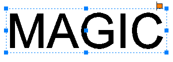 |
 [Vertical text] [Vertical text] |
Arrange characters vertically. |
 |
Move the selected character horizontally (left, right).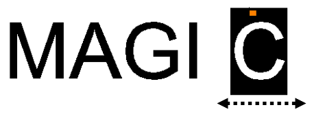 |
 |
Move the selected character vertically (up, down).  |
 |
Adjust the width of the selected character. |
 |
Rotate the selected character. |
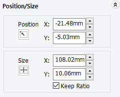 [Position/Size]
| Position | Designate the location of the selected object |
| Size | Designate the size of the selected object |
| Keep Ratio | Click “check” to maintain the same ratio for the object’s width and height. Click “uncheck” to adjust the object’s width and height separately. |
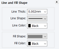 [Line and Fill Shape]
| Line Thick | Line thickness of the selected object |
| Line Shape | Line type of the selected object |
| Line Color | Line color of the selected object |
| Fill Shape | Color filled inside of the selected object |
| Fill Color | Shape filled inside of the selected object |
¶ 3) Rotation tool property
If the selected object is clicked once more, the mode will switch over to object rotation mode.
[Rotation]
 |
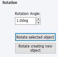
Designate the rotation angle of the selected object. Enter the desired angle of rotation or click the up/down arrow buttons. |
 |
Rotate selected object according to the angle entered. |
 |
Add a new object and rotate it according to the angle entered. |
¶ 4) How to engrave for each toolpath
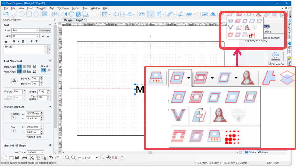
What is a Toolpath?
Toolpath is a path where the tool passes by for marking.
Toolpath is usually displayed in red color and the marking tool moves along the path as it engraves.
 |
[Cut-out toolpath] | Creates a toolpath that will cut out the selected object. The toolpath boundary will be wider than the boundary of the selected object depending on the thickness of the tool. *This toolpath must be used when cutting.  |
 |
[Outline toolpath] | Creates a toolpath that will engrave the outline of the selected object. |
 |
[Hatching toolpath] | Creates a toolpath that will engrave the inside of the selected object. |
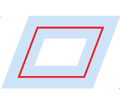 |
[Single line toolpath] | Creates a toolpath that will engrave the center line of the selected object. “Single line toolpath” process may cause deviation on center line. It is recommended to use fonts with thinner lines to reduce deviation. |
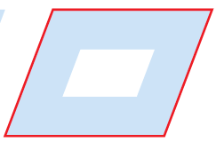 |
[Boundary-line toolpath] | Creates a toolpath that will engrave the boundary of the selected object. |
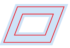 |
[Inline toolpath] | Creates toolpath that will engrave inline of the selected object. The toolpath is created within the borders of the selected object. 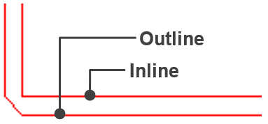 |
 |
[V-cut toolpath] | Creates a toolpath that will engrave V-cut groove. |
 |
[Convert object to toolpath] | Convert the selected object to toolpath. It’s not necessary to set toolpath settings each time. It will be automatically set to its preset values. 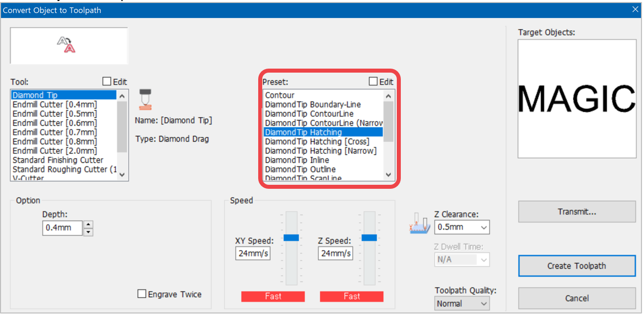 |
 |
[Photo impact engraving toolpath] | Creates a toolpath that will engrave an image with dots.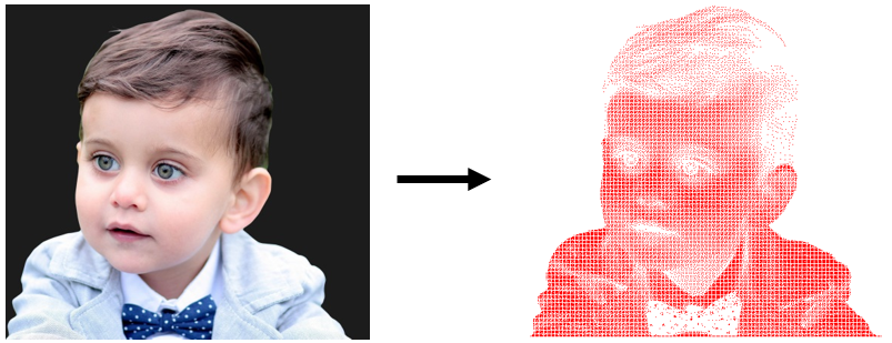 |
 |
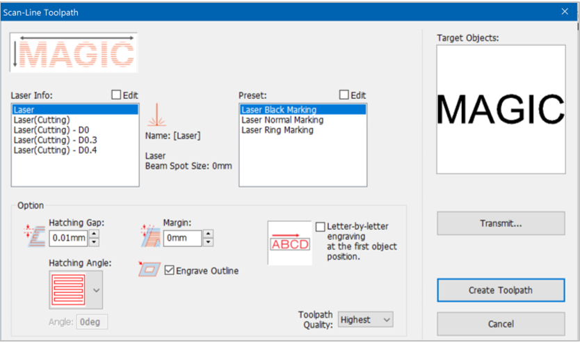
[Scan-line toolpath] | Creates toolpath that will engrave inside area of the selected object’s boundary. “Scan line toolpath” may appear similar to “Hatching toolpath” but it is specifically used to engrave on logos, patterns or objects with larger areas.  |
 |
[Contour line toolpath] | Creates a toolpath that will engrave the selected object with contour lines. |
 |
[Photo halftone engraving toolpath] | This converts an image into a half-toned image and engraves the object in dots or horizontal lines using a V-cut tool. This process is only applied to engraving machines with rotating-spindle function like Magic E7, E4 etc. 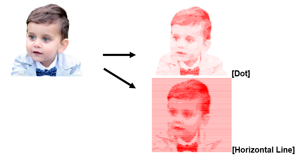 What is Half-toned Engraving? Half-toned engraving converts light and dark areas of a picture or an image into lines or dots in different sizes to express a fine image. |
 |
[Simulate toolpath processing] | Click this button to see the predicted image result of the toolpath processed by the selected tool. |
 |
[Show toolpath only] | Click this button to make the toolpath the only visible object on the screen (while all the other objects are temporarily hidden). Click this button again to reveal the other objects.  |
¶ 5) Create toolpath
¶ (1) Laser beam
¶ Add/Delete/Edit
Select the laser beam. Each engraving option value can be changed by pressing Edit or Add button.
Check “Edit” button to see Add/Delete/Edit buttons.
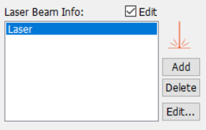
| [Add] | Designate a name for the tool to be added along with its type and other options like tip width, then click “OK” button. The tool will then be added to the tool selection list.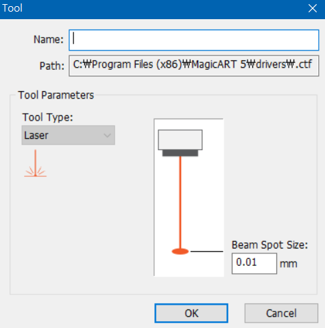 |
| [Delete] | Select a tool to be deleted then click “Delete” button to remove the tool from the list. |
| [Edit] | Select a tool to modify then click “Edit” button. Click “OK” button to save the modified value. |
¶ (2) Preset
¶ Add/Delete/Edit
Hatching angle, gap and others are pre-set for each engraving option. Therefore, it is not necessary to designate hatching gap, angle and others every time and they will be automatically set with their pre-set values. Each engraving option value can be changed by pressing Edit or Add button.
Check “Edit” button to see Add/Delete/Edit buttons.
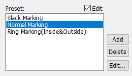
| [Add] | Designate a name for the tool to be added along with its type and other options like tip width, then click “OK” button. The tool will then be added to the tool selection list.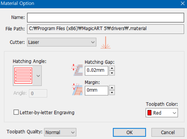 |
| [Delete] | Select a tool to be deleted then click “Delete” button to remove the tool from the list. |
| [Edit] | Select a tool to modify then click “Edit” button. Click “OK” button to save the modified value. |
¶ Option
| Hatching gap | Designate hatching gap.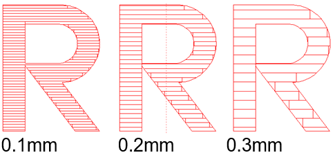 |
| Margin | Designate a margin between object outline and toolpath.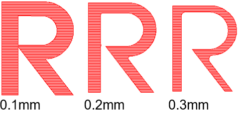 |
| Direction | The following hatch lines are applied to hatching toolpath only: : A tool path is created in the horizontal directions : A tool path is created in the horizontal directions  : A tool path is created in the vertical directions : A tool path is created in the vertical directions  : A tool path is created in the left diagonal directions : A tool path is created in the left diagonal directions  : A tool path is created in the right diagonal directions : A tool path is created in the right diagonal directions  : A tool path is created in the diagonal cross hatched directions : A tool path is created in the diagonal cross hatched directions 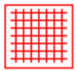 : A toolpath is created in horizontal and vertical directions : A toolpath is created in horizontal and vertical directions ※ These toolpaths are not recommended to be applied to materials with plated surfaces as they may cause possible damage to the material. |
| Engrave outline | If this option is checked, a toolpath with an outline is created. If unchecked, a toolpath without an outline is created.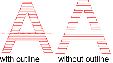 |
| Letter-by-letter engraving at first object position | After marking the first letter, it waits, then marks the next letter and repeats the process until all letters are marked in sequential order. Here, the user manually adjusts the marking position of each letter after each marking. (For example: If the letters to mark are ABC, enter the number of characters to mark (e.g., ‘1’) in input then the machine will start to mark each letter by sequence. Once letter ‘A’ is marked, the user manually adjusts the marking position of the next letter then the machine proceeds to mark the next letter which is ‘B’, repeats the same process then marks ‘C’. 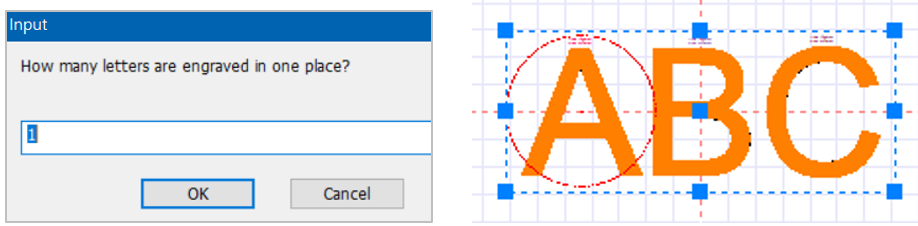 |
| Toolpath quality | Select the toolpath quality. The higher quality, the longer toolpath creation time. |
| Transmit | Toolpath output window is displayed. |
¶ (3) Convert object to toolpath
 |
Convert the selected object to toolpath. It’s not necessary to set toolpath settings each time. It will be automatically set to its preset values. |
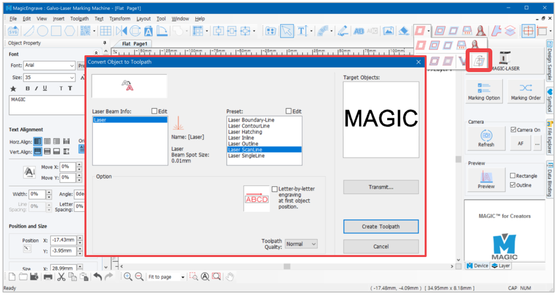
¶ Laser Beam Info: Add/Delete/Edit
Check “Edit” button to see Add/Delete/Edit buttons.
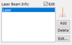
| [Add] | Designate a name for the tool to be added along with its type and other options like tip width, then click “OK” button. The tool will then be added to the tool selection list.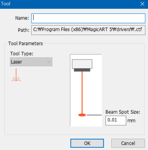 |
| [Delete] | Select a tool to be deleted then click “Delete” button to remove the tool from the list. |
| [Edit] | Select a tool to modify then click “Edit” button. Click “OK” button to save the modified value. |
¶ Preset: Add/Delete/Edit
Toolpath setting pre-set for each toolpath. Therefore, it is not necessary to designate hatching gap, angle and others every time and they will be automatically set with their pre-set values. Each toolpath setting value can be changed by pressing Edit or Add button.
If “Edit” button is checked, Add/Delete/Edit buttons will appear.
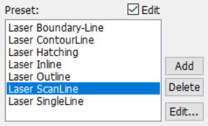
| [Add] | Designate a name for the tool to be added along with its type and other options like tip width, then click “OK” button. The tool will then be added to the tool selection list.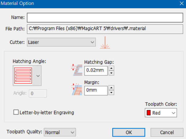 |
| [Delete] | Select a tool to be deleted then click “Delete” button to remove the tool from the list. |
| [Edit] | Select a tool to modify then click “Edit” button. Click “OK” button to save the modified value. |
¶ 6) Laser option
¶ (1) Quick Setting
Once the toolpath is created, you can set the laser marking options in the object property window then proceed to immediate marking by clicking the [Laser] button.
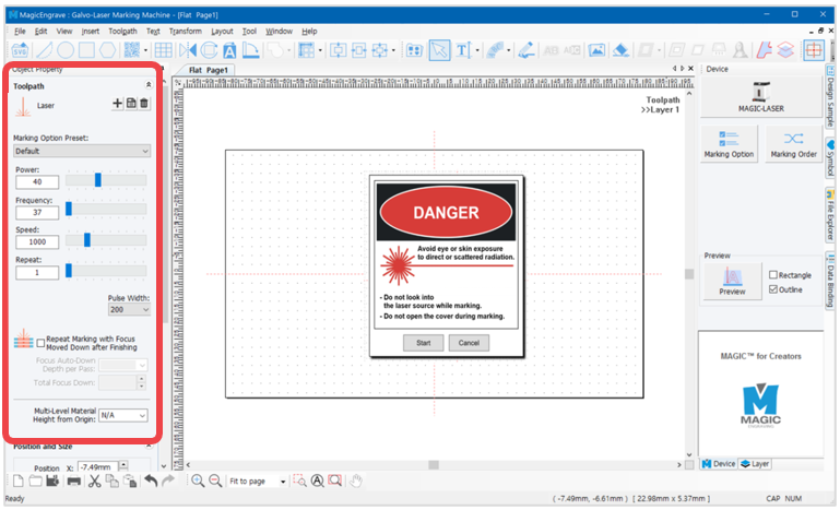
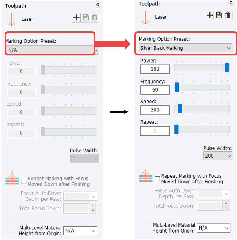
| Marking Option Preset | Selects the marking option ※See details below. |
| Power | Adjusts the laser power. |
| Frequency | Adjusts the laser frequency. |
| Speed | Adjusts the marking speed. |
| Repeat | Adjusts the marking repetition. |
| Pulse Width | Adjusts the pulse width. |
| Repeat Marking with Focus Moved Down after Finish |
Sets the marking depth when setting up Deep Marking. ex) 0.05mm per marking, 2 times - Auto lowering depth after marking :0.05mm - Z auto lowering total depth: 0.1mm |
| Multi-Level Material Height from Origin | Batch engraving on materials with multi-heights. Enter the heights from the focus surface to marking surface in the program, then the system adjusts focus according to the material heights automatically and performs engraving. ex) Marking moves up by 1mm ※See details [Multi-Height Auto Leveling Marking]. |
¶ Add/Edit and Save/Delete
Laser options such as power and speed can be set in advance.
Click [Edit and Save] then click the button at the bottom to change options.
¶ (2) Marking option window
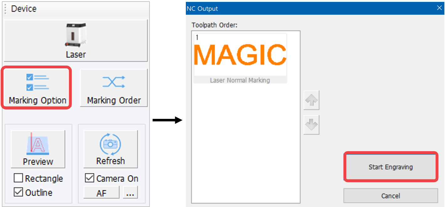
After creating the toolpath, click [Marking Option] button to set the laser option. In the NC Output window adjust the laser option then click [Start Engraving].
In the Laser Option window, you can select the preset engraving options and adjust the laser options. Click [Save As] to save the options.
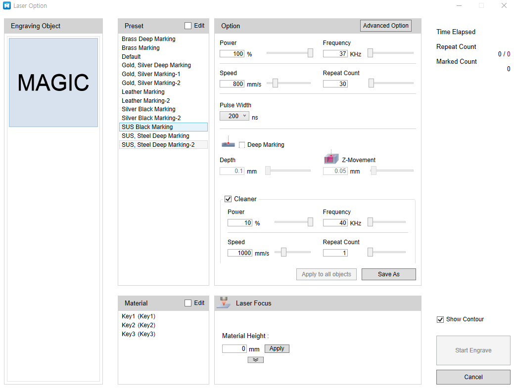
| Engraving object | Checks the object to engrave | ||
| Preset | Selects the marking option※See details below. | ||
| Option | Changes the laser option ※See details below. | ||
| Advanced Option | Changes the advanced option | ||
| Power | Adjusts the laser power | ||
| Frequency | Adjusts the laser frequency | ||
| Speed | Adjusts the speed | ||
| Repeat Count | Adjusts the repetition | ||
| Pulse Width | Adjusts the pulse width | ||
| Deep Marking | Depth | Adjusts marking depth upon selection of Deep Marking | |
| Z-Movement | The depth specified upon selection of Deep Marking is not marked at once but is divided and adjusted by Z-axis moving unit. E.g.) Deep Marking-specified depth: In the event of 1.2mm/0.3mm Z-axis moving unit, a depth of 1.2mm is marked (0.3mm per marking, 4 times). | ||
| Cleaner | Polishes the material after marking | ||
| Material | Selects the preset marking height ※See details below | ||
| Laser Focus | Material height | Sets the height of the material. The laser focus is adjusted according to the height of the material. It can also be set by entering the material height | |
| Show Contour | Instead of checking your design on the work area, use ‘View Contour’ function to preview your design.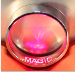 Ex) L-type clamp internal diameter Ex) L-type clamp internal diameter |
||
¶ Preset
Set the laser options in advance.
Select [Edit] then click the button at the bottom to change options.
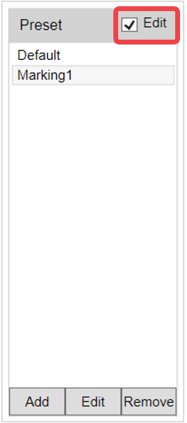
-Add
Add a new marking option.
Set the options and click [Save].
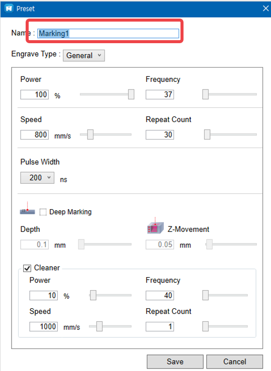
-Edit
Edit marking options.
Edit the options and click [Save].
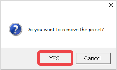
-Remove
Remove marking options.
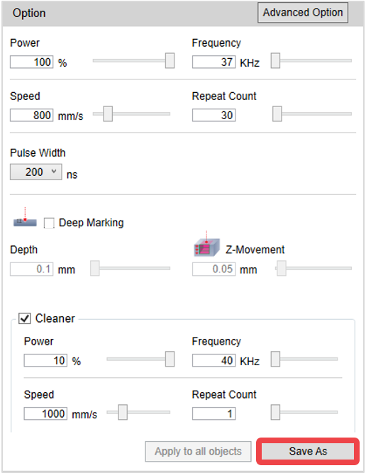
¶ Options
Laser options can change depending on the marking type. Select a marking type, adjust the laser options value then click [Save as].
¶ Material
The height of laser focus can be set by material.
Select [Edit] then click the button at the bottom to change options.
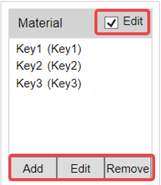
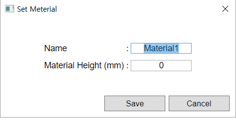
-Add
Add new material settings.
Set the name and material height and click [Save].
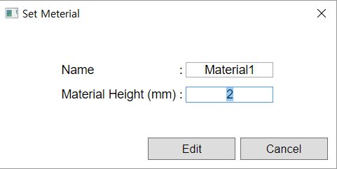
-Edit
Edit material settings.
Edit the options and click [Save].
-Remove
Remove material options.
¶ Rotary Engraving Option
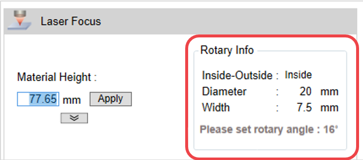
When laser marking with a rotary, the diameter and width input of your design in the MagicEngrave program is applied and displayed as it is. The laser focus is automatically set using the values entered.
For auto-tilt rotary clamp, the device auto calculates the height based on the titled angle when marking on the inside or outside of a rounded material.
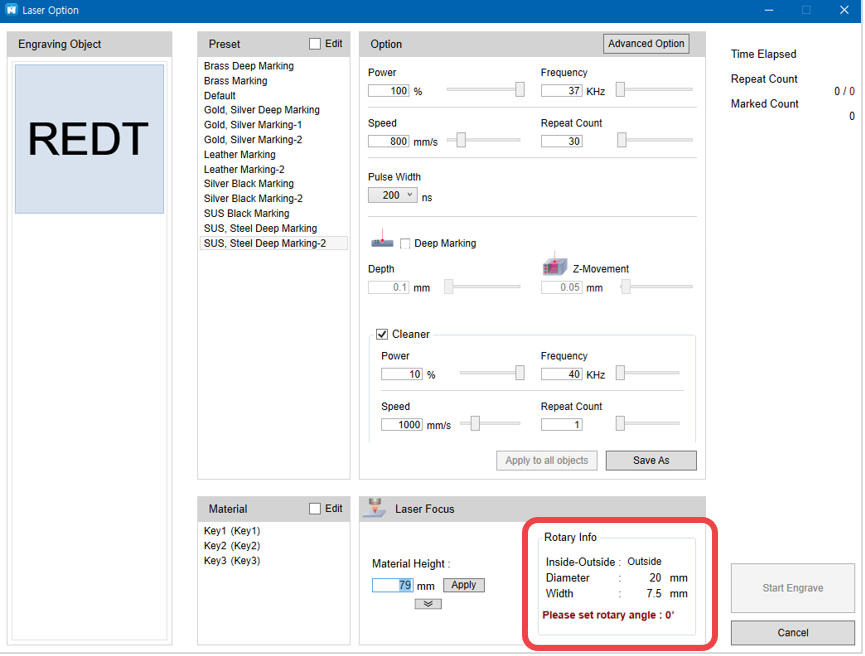
When marking on the inside of a rounded material, the device calculates the angle then sends a notification.
¶ Laser Option by Toolpath
Laser options vary depending on the Toolpath created.
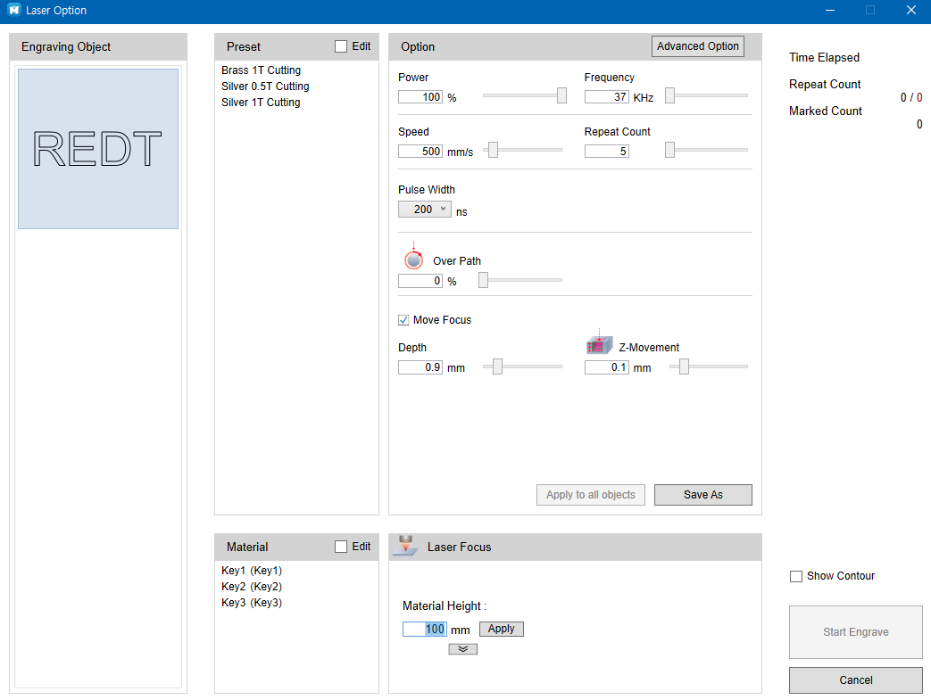
-Cutting Toolpath
•Overpath: Laser cutting with the set value past the cutting start point for enhanced cutting quality.
•Move Focus: Similar to focus depth setting: designate the depth when cutting the depth little by little.
depth.
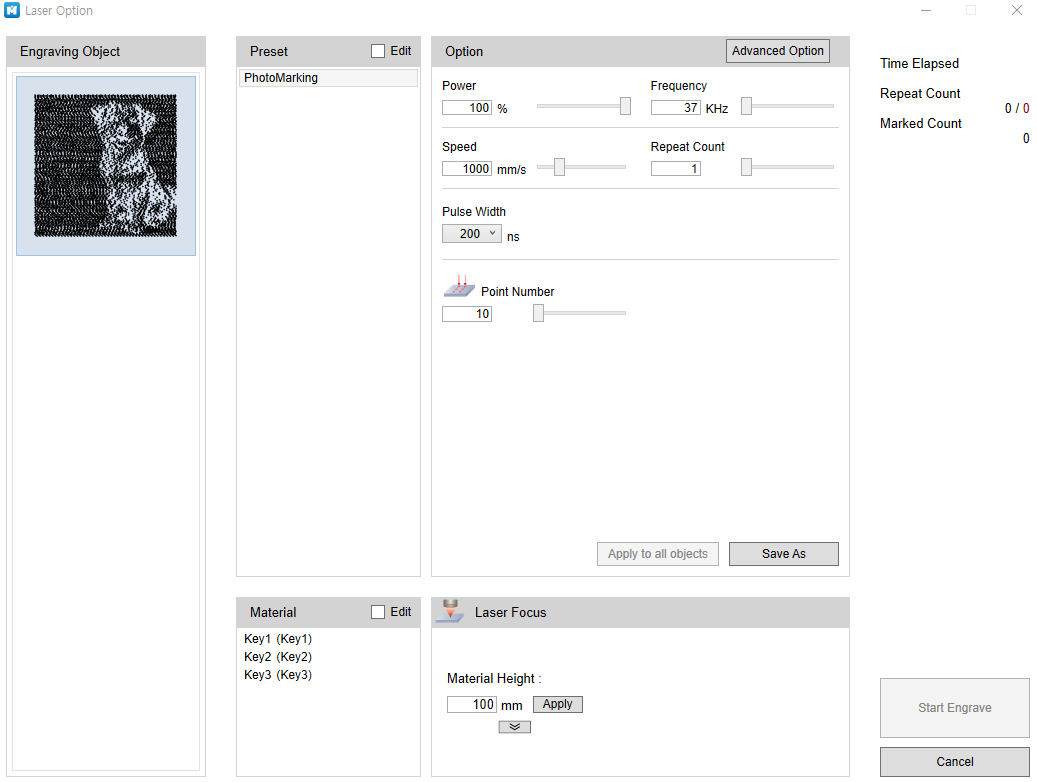
-Image Marking Toolpath
•Number of Points: For image marking, the image is laser marked with tiny points. The number of points to mark on the image at once is already set by default. You may adjust the number of points to achieve enhanced marking quality.
¶ 7) Data output
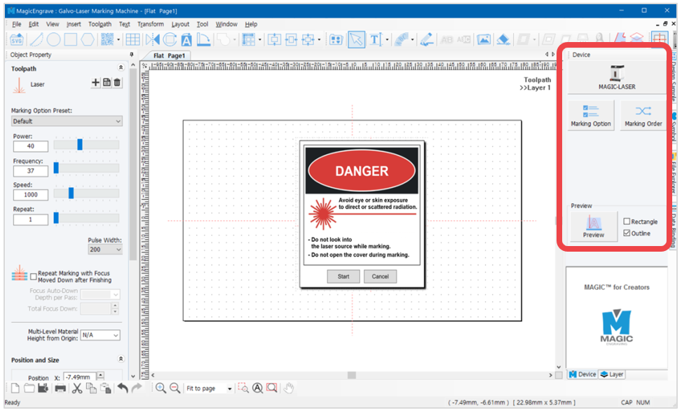
Select a Toolpath then click the  button on the top-right of the screen to transfer the data of the selected toolpath to the machine.
¶ (1) LASER
After creating the toolpath, set the engraving option. Then, click the [Laser] button to send the marking data.
¶ (2) Marking option

Click the [Marking Option] button to set the laser option. (✽See Laser option for details.)
¶ (3) Marking order

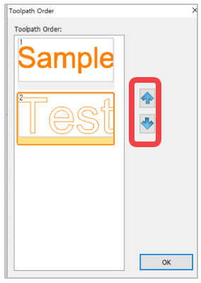
The Toolpaths are put in order if two or more are selected for marking.
The order can be changed by clicking [Up] and [Down] buttons on the right.
¶ (4) Camera
Activate the camera. L3 has a built-in camera that enables actual viewing of the marking area. The camera captures actual images of the material then sends the images to the program along with the size and position of the material (on the work area), allowing users to directly create designs by viewing the actual image of the material and designate a specific size and location to mark.
✽L3 Viewing area: 80mm x 80mm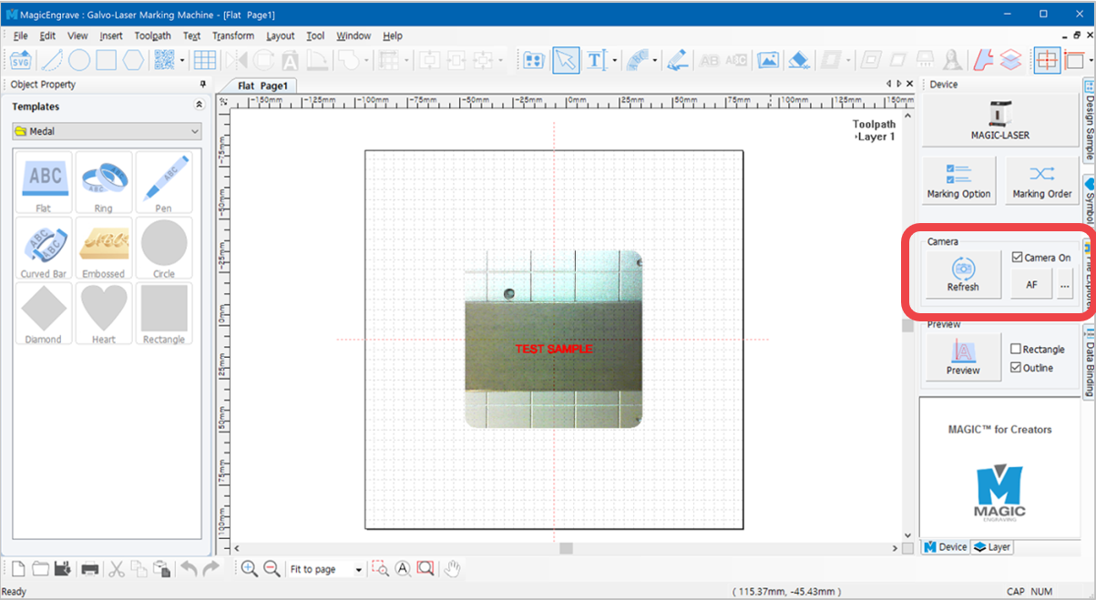
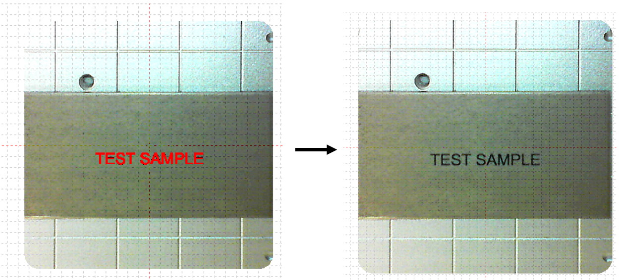
The laser must be focused in order to use auto positioning properly.
Since the camera is calibrated based on the focus of the laser, the accuracy of auto positioning is reduced if the laser is out of focus.
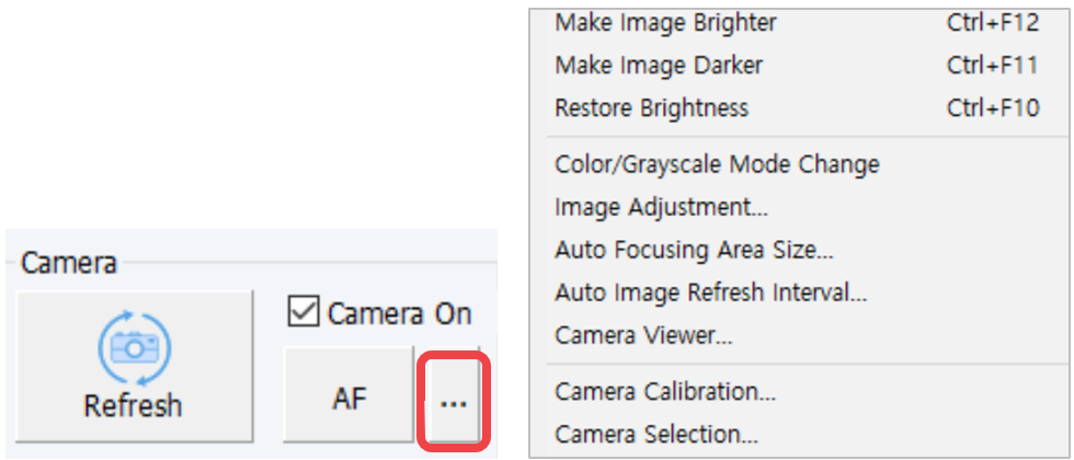
| Refresh | Renew the camera image displayed in the MagicEngrave Program. |
| Camera On | Activate/Inactivate the camera function. When [Camera on], auto positioning is also activated. |
| AF | See [8. Auto Focus] for details. |
| Make Image Brighter | Set the camera image brighter. |
| Make Image Darker | Set the camera image darker. |
| Restore Brightness | Restore the camera brightness. |
| Color/Grayscale Mode Change | Change image mode to Color or Grayscale. |
| Image Adjustment | Set the camera image options such as contrast, grayscale etc.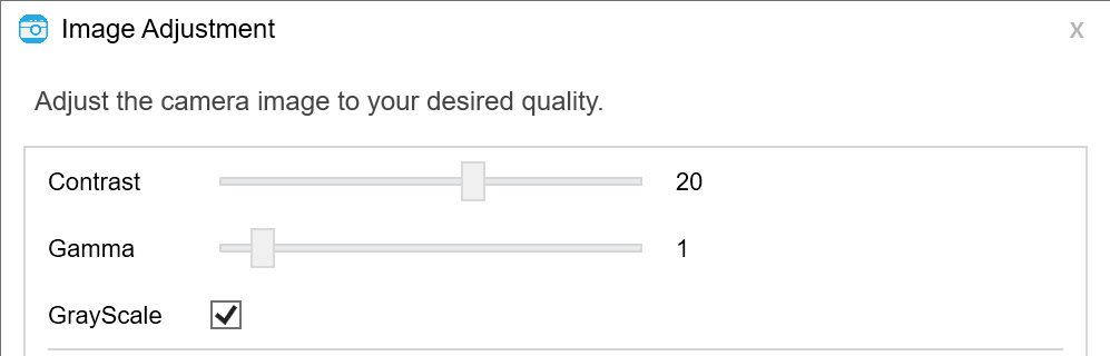 |
| Auto Focusing Area Size | Set the size of the camera image displayed in the program. ✽Take note that the size of the camera image cannot exceed the maximum area of the camera function supported by the machine. 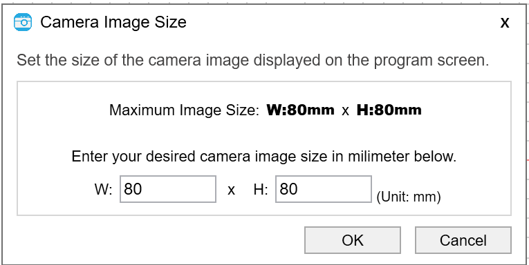 |
| Auto Image Refresh Interval | Set the auto image renewal interval displayed in the program. - Setting range: min. 5 sec. ~ max. 30 sec. 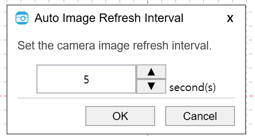 |
| Camera Viewer | View the camera image in a new window.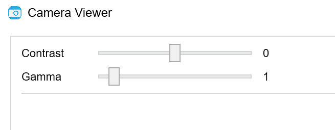 |
| Camera Calibration | See [Machine setting] → [7. Camera] |
| Camera Selection | Select your camera device. The camera for laser is set automatically even if there are multiple default camera devices connected to the PC. The camera device can also be selected manually. 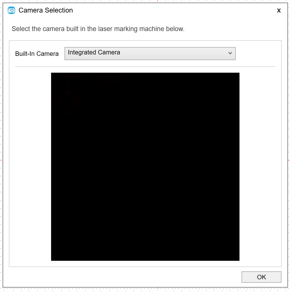 |
¶ (5) Preview
Select the object then click [Preview] button to preview the marking area.
✽This function is only available after selecting the object.
✽In the preview, you can use the arrow keys to change the position of the marking area. (However, this is not possible when auto positioning function is activated.)
The preview icon changes once selected.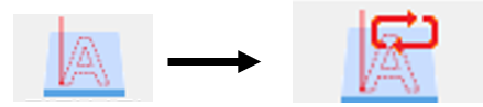
| Rectangle | The marking area is indicated by a rectangle. However, rotary marking is only available for Rectangle preview. |
| Outline | The marking area is indicated by an object outline. |
¶ 8) Auto focus
MAGIC™-L3 has a built-in auto focusing system that auto focuses on the surface area of the material to mark with the use of a material height-sensing camera.
✽Auto focus maximum measurement height: 55mm
✽Precision: 0.5mm
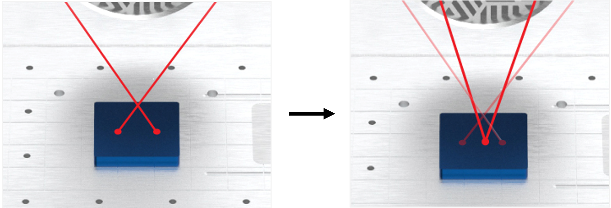
*Auto focus is an auxiliary function; the laser focus must be set when using auto focus.
*Auto focus is not available for rotary marking.
Auto focus may be unavailable or less accurate depending on the characteristics of the material.
※The conditions are summarized as follows;
-Materials that scatter laser light (Ex: Bakelite, white acryl, etc.)
-Materials that do not absorb laser light (Ex: Transparent acryl, glass, etc.)
-Red-colored materials that resemble the color of the laser light (Ex: Red-color anodizing aluminum, etc.)
-Mirrored-surface materials with high reflectivity (Ex: Chromium-plated pendants, etc.)
-Other materials where laser light appears invisible.
-Other materials on which the focus pointer is not clearly seen.
- Click the [AF] button on the top right of the screen.
Or press the  button on the L3 machine.

- View the camera image in a new window.
When autofocus initializes, the program displays the progress of the function on the screen.
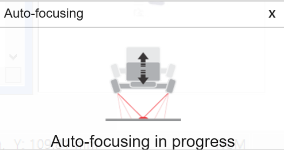
The progress of the autofocus function is also displayed on the LED screen.

- To cancel autofocus function, press
 button on the L3 machine.