Calibrate rotary origin if rotary clamp is in use.
¶ How to calibrate rotary clamp origin
- Place and secure the rotary clamp to the work area.
- Click [Rotary Origin].
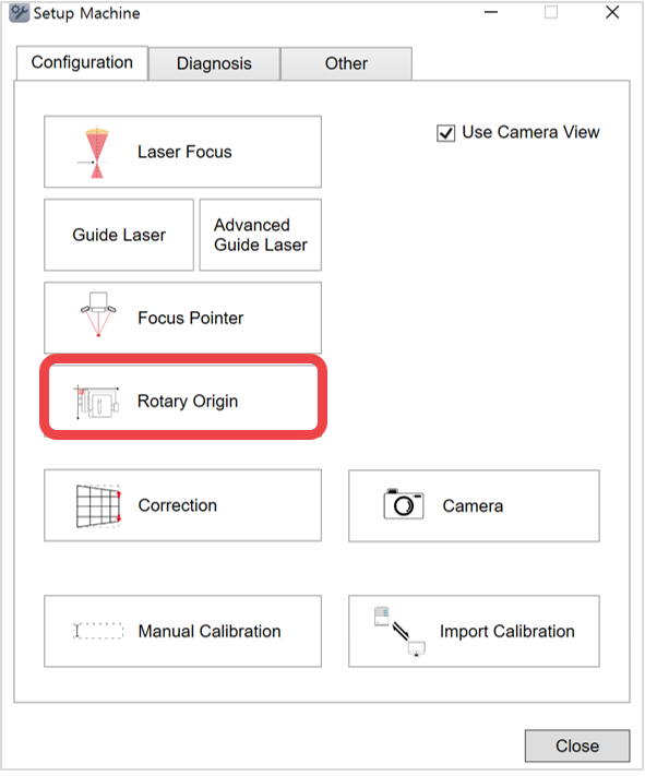
- If rotary clamp auto tilting function is enabled, first, set the tilting origin to 0 degree.
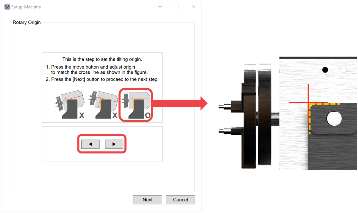
¶ How to set the tilting origin to 0
Match the clamp angle with the cross mark on the clamp body (as shown above).
Click  up/down button to adjust the angle by 0.1 degree.
Once the angle is positioned to 0 degree, click [Next].
| Setting tool | 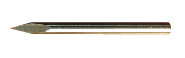 |
1EA | Tool for rotary origin setting. |
- Insert the setting tool into the rotary (as shown below).
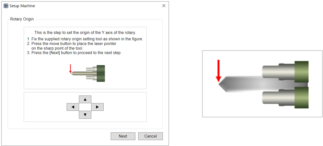
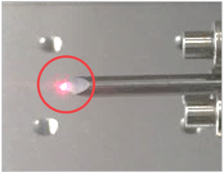
- Match the tip of the tool to the laser pointer. Use the direction key buttons to position the laser pointer to tip of the tool. Then, click [Next].
Or, on the machine, use
 buttons then long-press
  button (for more than 1 second).
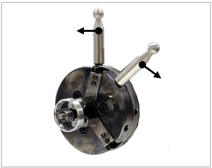
- Remove the setting tool then insert the ring into the finger chuck (as shown below). Use both finger chuck handle to tighten the clamp and secure the ring.
- Then, move to the next step. Enter the size of the ring.
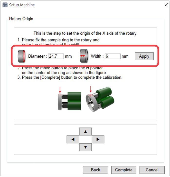
- Move the [H pointer] to the center of the ring by using the direction key buttons. Then, click [Complete].
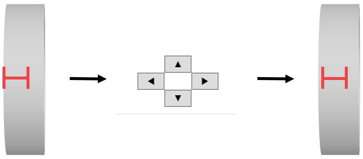
¶ How to calibrate bangle clamp origin
- Place and secure the bangle clamp to the work area.
- Click [Rotary Origin].
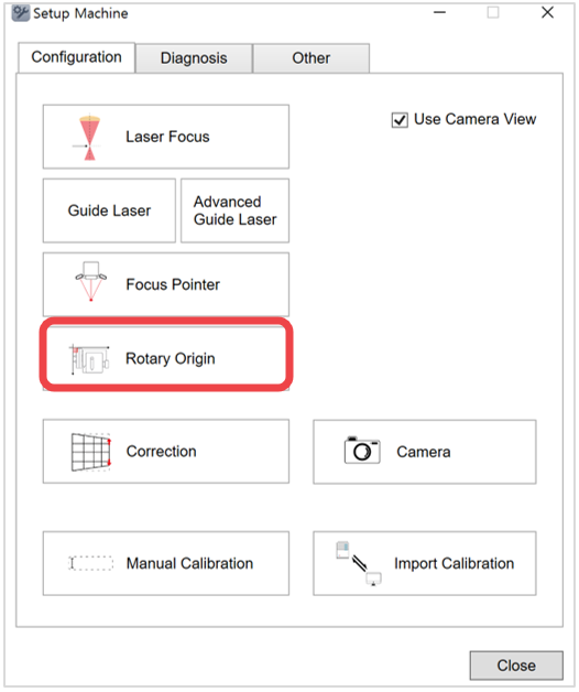
- If bangle clamp auto tilting function is enabled, first, set the tilting origin to 0 degree.
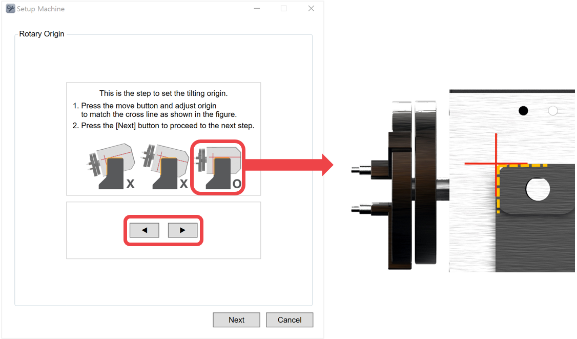
Match the clamp angle with the cross mark on the clamp body (as shown above).
Click up/down button to adjust the angle by 0.1 degree.
Once the angle is positioned to 0 degree, click [Next].
※Unlike the rotary clamp, adjusting the left-right position saves the setting permanently, even after restarting the program.