1. Place and secure the rotary clamp to the work area.
2. Click [Rotary Origin].
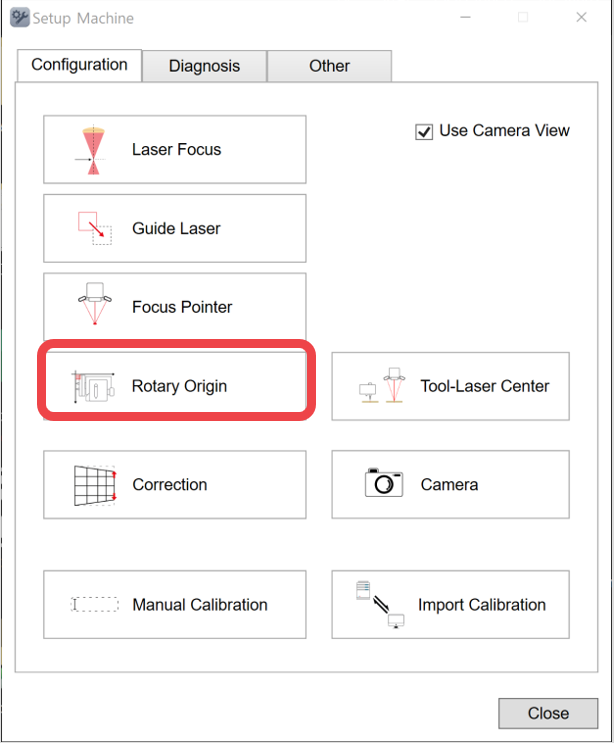
3. The process consists of two steps: setting the Y-axis origin and setting the X-axis origin.
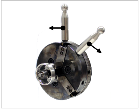
4 [Y-axis origin setting] Secure a pointed tool in the rotary clamp as shown in the figure below.
| Setting tool | 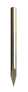 |
1EA | Tool for rotary origin setting. |
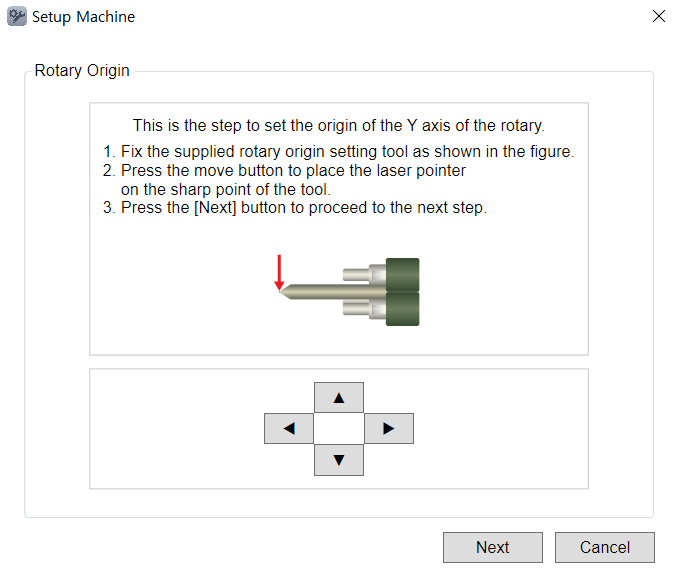
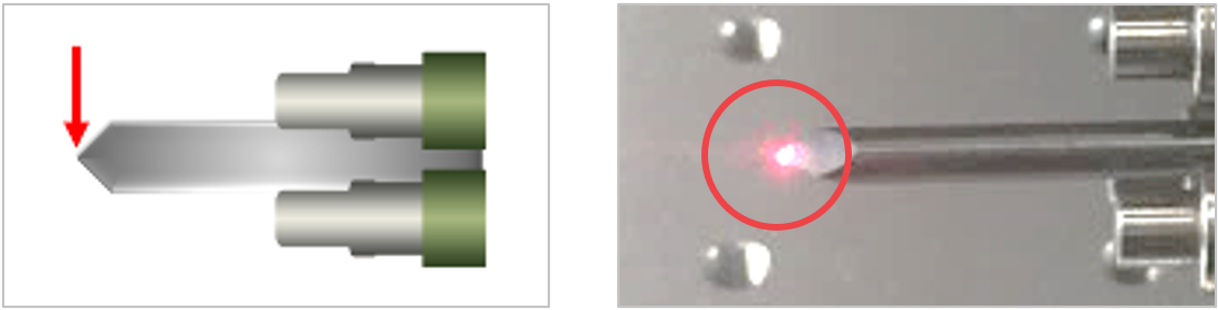
5. Match the tip of the tool to the laser pointer. Use the direction key buttons to position the laser pointer to tip of the tool. Then, click [Next].
Or, on the machine, use 
 buttons then long-press
  utton (for more than 1 second).
6. Remove the setting tool then insert the ring into the finger chuck (as shown below). Use both finger chuck handle to tighten the clamp and secure the ring.
7. [Proceed with X-axis Origin Setting] Secure the calibration material, enter the diameter and height, and press the [Apply] button.
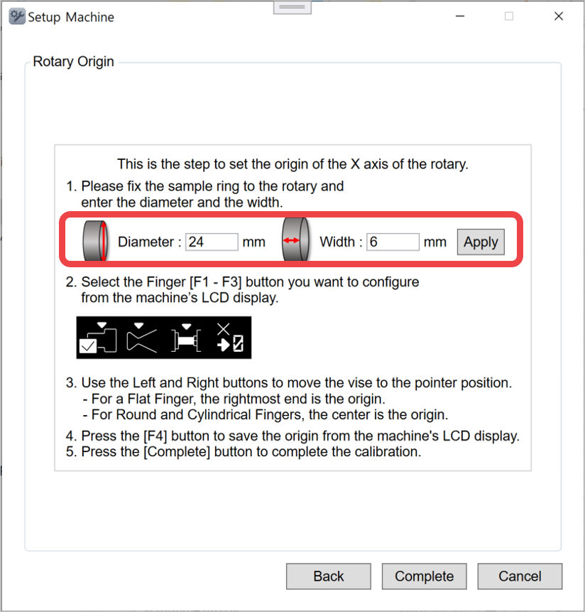
8. On the marking machine LCD screen, press the F1–F3 buttons to select the desired finger.
9. Press the Left/Right direction buttons on the marking machine to move the clamp and adjust the position.
• For the flat finger, the right end is the origin.
• For the round and cylinder fingers, the center is the origin.
10. Press the F4 button on the marking machine keypad to save the origin.
The origin must be saved for each finger individually.