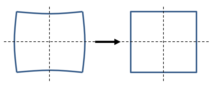
The father the laser moves away from the center, the greater the distortion occurs. When the laser passes through the lens after passing through the scan head, the farther it moves, the more distorted the shapes become (see figure on the left). To correct distortion, correction process is used (see figure on the right).
¶ How to calibrate correction
1. Use a material larger than (110x110 mm). Preferably, with a size of (120x120 mm).
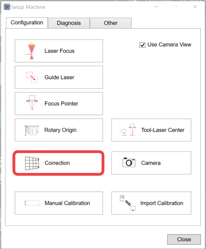
2. Click [Correction].
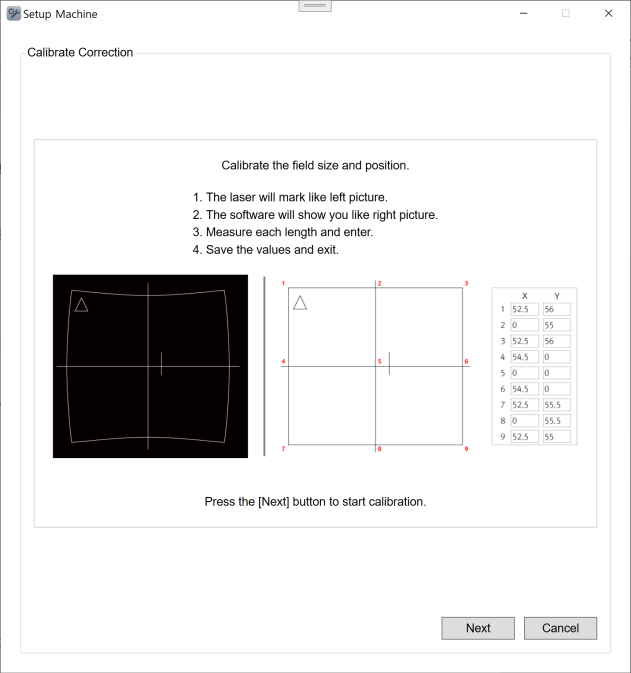
3. Read the notification on calibration process. Click [Next] to start calibration.
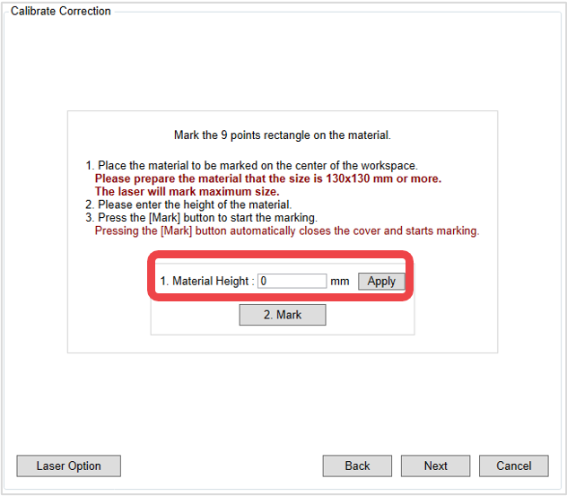
4. Enter the height of the material then click [Apply]. Click [Mark] to start marking.
5. Measure the coordinate values in each corner. Enter the sizes then click [Complete] to finish calibration.
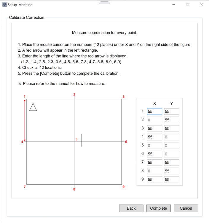
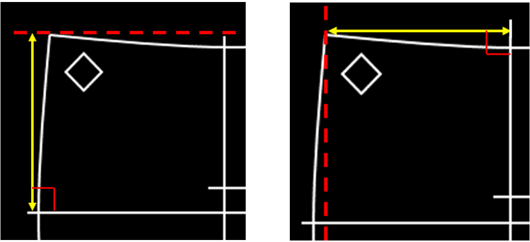
Be sure to measure the size from each corner (as shown below).