[Use camera view]
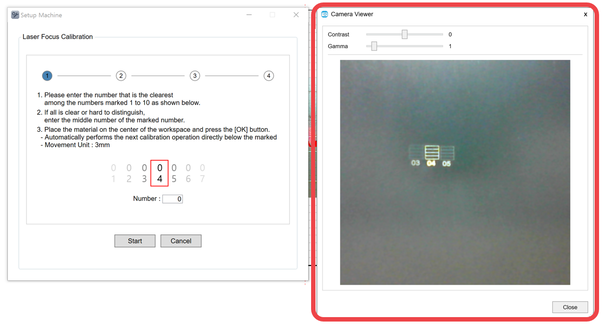
Select the checkbox (on the top right corner) to display Camera Viewer.
Use Camera Viewer to accurately check and calibrate each setting.
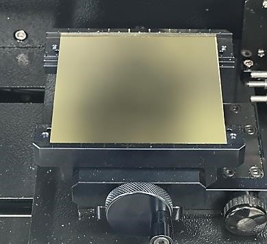
1. Place the material on the work area.
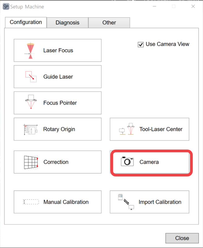
2. Click [Camera].
3. Enter the height of the material (to mark a rectangle), then click [Apply]. After clicking the [Mark] button, manually close the machine cover. An 80 × 80 mm rectangle will then be marked on the material.
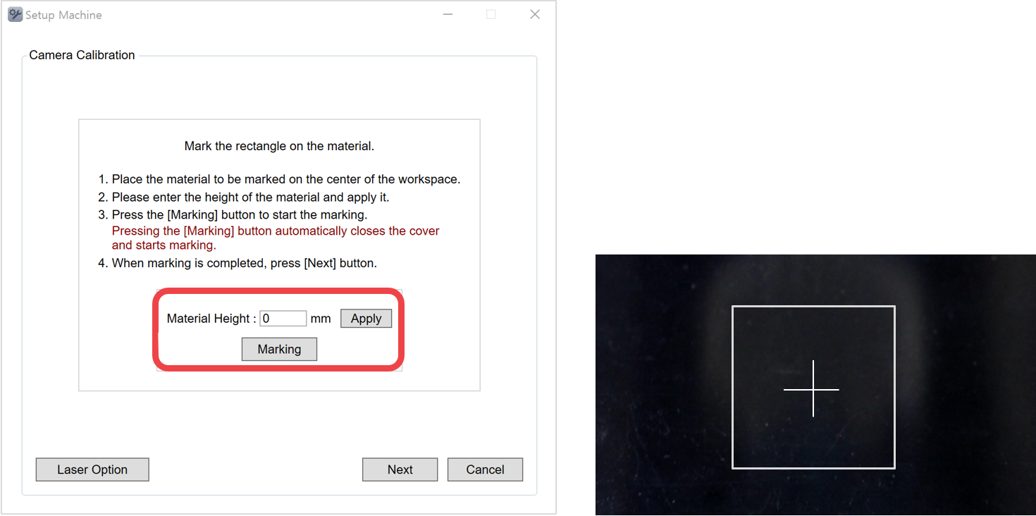
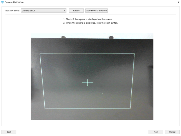
4. Check the camera window then click [Next].
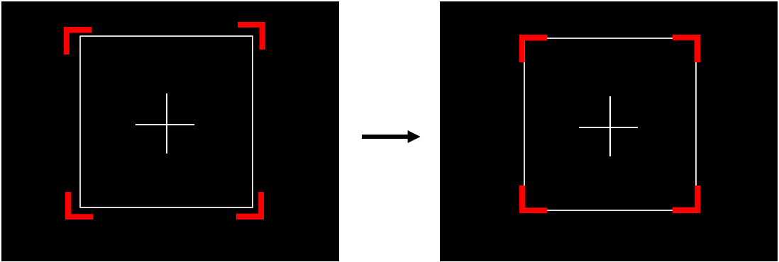
5. Align the four red borders to each corner of the marked rectangle.
Use your mouse to align the red borders and set their approximate position to the corners of the rectangle. Use the arrow keys on your keyboard to adjust and set the position of each red boarder. Once the red borders are aligned to the corners, click [Next].
 |
| [Camera screen] |
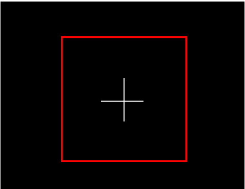
6. Check whether or not the red border matches the marked border on the camera screen. If the red border appears misaligned or unmatched, go back to step 5 and readjust its position.
 |
| [Camera screen] |
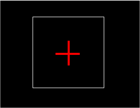
7. Check whether or not the red [+] cross mark matches the marked [+] cross on the camera screen. If the red cross mark appears misaligned or unmatched, use the arrow keys on your keyboard to adjust its position. Then, click [Next].
 |
| [Camera screen] |