¶ Contents
- 1. Machine Descriptions for the JANUS
- 2. Head
- 3. Clamp
- 4. Keypad
- 5. Menu
- 6. Display
- 7. Status indicator
¶ 1. Machine
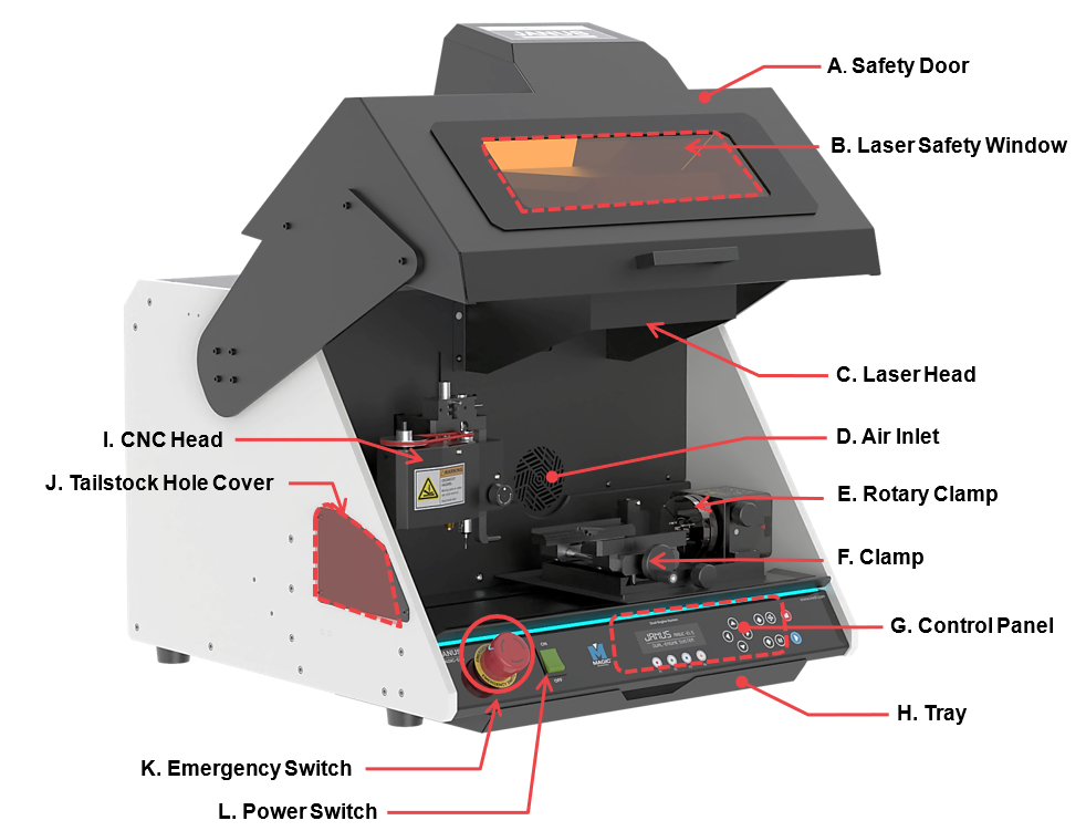
| A | Safety Door | Opens/closes the cover |
| B | Laser Safety Window | Protects the eyes from being exposed to laser light ※Wavelength protection: 1064nm/Optical density: OD6 |
| C | Laser Head | Emits the laser beam for marking and engraving
 ※Do not stare at specular or diffuse laser reflections. Doing so may cause permanent eye injury or blindness. |
| D | Air Inlet | Draws in fumes and particulate matter generated during marking |
| E | Rotary Clamp | Rotary clamp for holding cylindrical materials |
| F | Clamp | Clamp for holding the material in place |
| G | Control Panel | Controls the power switch and provides manual controls for marking operations |
| H | Tray | Lower Tray |
| I | CNC Head | CNC head for holding cutting tools and engraving tips |
| J | Tailstock Hole Cover | Supports the material and helps hold it in place during rotary engraving |
| K | Emergency Switch | Stops the machine during emergency |
| L | Power Switch | Turn on/off the power switch |
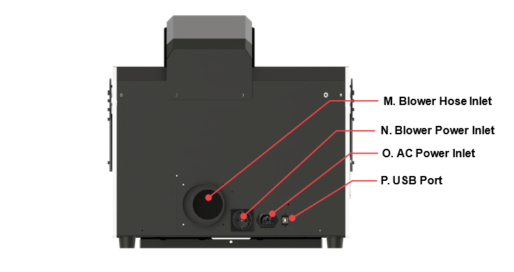
| M | Blower Hose Inlet | Connects the blower hose to the outlet to remove dusts and debris produced during marking operation |
| N | Blower Power Inlet | To supply power to the blower by connecting it to the machine <110~220V/2A> ※Auxiliary Power Device must be used if the external blower has more than 2 Ampere. |
| O | AC Power Inlet | To supply power to the machine ※Use a grounded outlet only. Do not plug the machine into an ungrounded outlet. |
| P | USB Port | To connect USB cable to PC |
¶ 2. Head
¶ 1) Laser Head
Emits the laser beam for marking and engraving.
Do not stare at specular or diffuse laser reflections. Doing so may cause permanent eye injury or blindness.
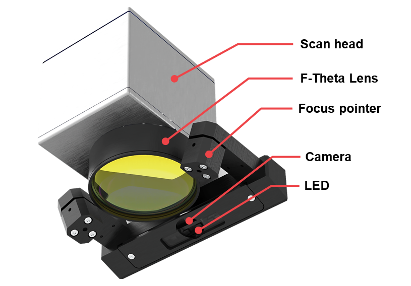
| Laser head | |
|---|---|
| Scan head | Scan head for laser marking. |
| F-Theta Lens | Lens for laser marking. |
| Focus pointer | Pointer for laser focusing |
| Camera | Camera for positioning during laser marking. |
| LED | LED for illumination. |
¶ 2) CNC Head
CNC head for holding cutting tools and engraving tips.

The tools of the machine are sharp, and may cause serious physical injury.
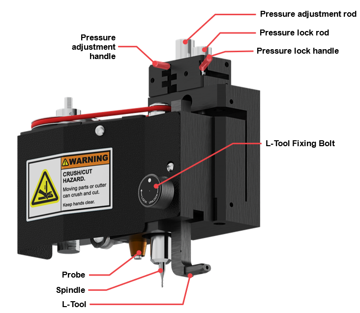
| CNC head | |
|---|---|
| Pressure adjustment rod | Supports pressure adjustment with the handle. |
| Pressure adjustment handle | Adjusts the pressure of the engraving tool. |
| Pressure lock rod | Supports pressure locking with the handle. |
| Pressure lock handle | Locks the pressure of the engraving tool. |
| L-Tool Fixing Bolt | Secures the L-tool. |
| Probe | Measures the height of the engraving material. |
| Spindle | Secures the tool for engraving. ※To change tools, use a 2mm T-wrench. |
| L-Tool | Secures the L-tool tip when engraving on the inside of rings or bangles. |
¶ Switching Tools
Do not let any of your body parts or any foreign objects get caught in the machine during operation.
The tools of the machine are sharp, and may cause serious physical injury.

Please wear safety glasses during engraving process for safety.
Debris like metal chips and dusts may cause serious eye injury if they get stuck in the eye.
¶ Spindle
| Name | Picture | Quantity | Usage |
| T-wrench (2mm) |
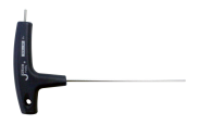 |
1EA | Tool for tightening/unscrewing of bolt. |
As shown below, insert the 2mm wrench into the fixing bolt. Turn the wrench to the left to unscrew bolt. To prevent the tool from falling to the floor, grab tool with your hand then pull it out. Once the tool is removed, replace it with a new tool then secure it using a wrench for tightening bolts. ※See package contents
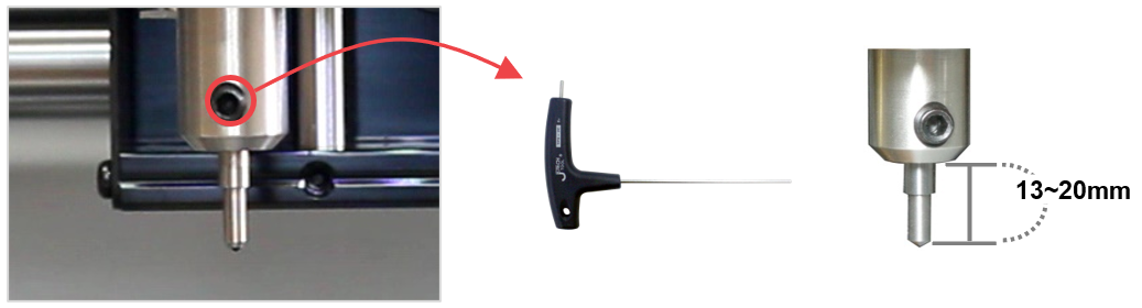
When unscrewing the tool fixing bolt, hold the tool with your hand while unscrewing to avoid the bolt from dropping on the floor.
¶ L-Tool
| Name | Picture | Quantity | Usage |
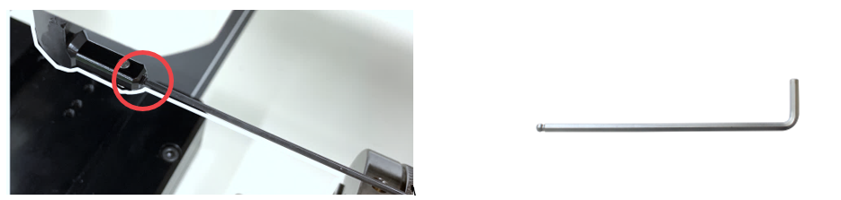
| L-wrench (1.5mm) |
 |
1EA | Tool for tightening/replacement of bolt. |
| L-tool fixing bolt (M3x4) |
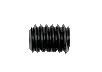 |
3EA | L-tool tip fixing bolt |
As shown below, insert the 1.5mm wrench into the fixing bolt. Turn the wrench to the left to unscrew bolt. To prevent the tool from falling to the floor, grab tool with your hand then pull it out. Once the tool is removed, replace it with a new tool then secure it using a wrench for tightening bolts. ※See package contents
¶ Pressure
When cutting or engraving with a V-cutter or end mill, lock the tension. This reduces vibration during operation, improves cutting and engraving quality, and extends tool life.
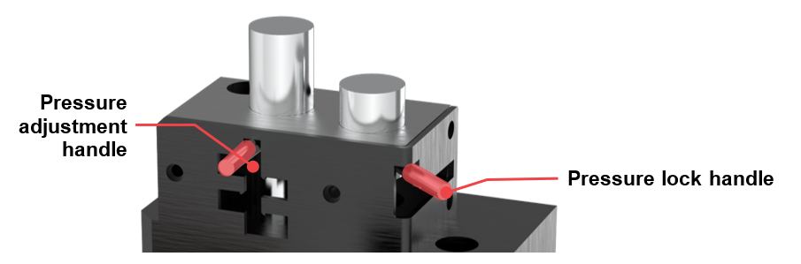
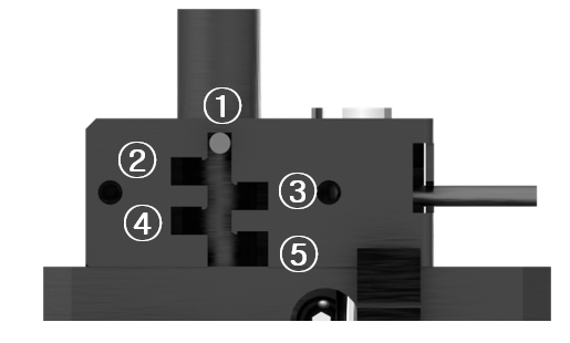
1. Position the pressure adjustment handle in the slot marked with a number, as shown in the image below, to set the head pressure according to the selected number.
(Order: 5 > 4 > 3 > 2 > 1, with 5 providing the highest pressure.)
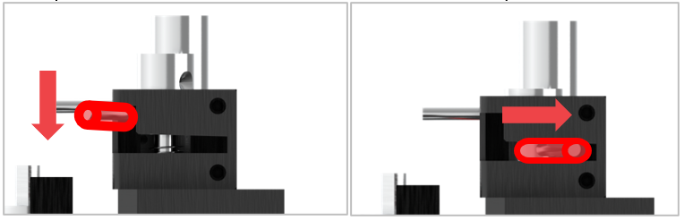
2. Push the pressure lock handle down and to the right, as shown below, to engage it in the groove and lock the head pressure. To release the lock, move the handle up and to the left.
¶ Spindle belt
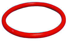 |
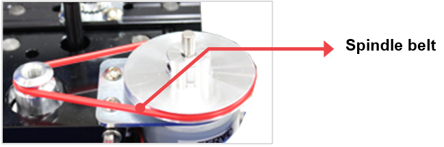
The spindle belt transmits the rotational force of the spindle motor to the spindle to enable fast rotation of the blades. Worn out spindle belts cause the surface to crack and slip, causing the spindle motor to fail or function properly. If the force is not transmitted properly, the spindle’s rotational speed will decrease, leading to poor engraving performance and quality. Additionally, a damaged spindle belt has the potential to cause the tool to break. |
• Spindle Belt Size: 60Ø (60mm)
• Replacement Cycle: The lifespan of the spindle belt is contingent upon the conditions of use, but it should be replaced at the latest every two to three months.
• Spindle Belt Replacement Method: You will see a red rubber belt attached around the head. Remove this belt then replace it with a new one.
¶ 3. Clamp
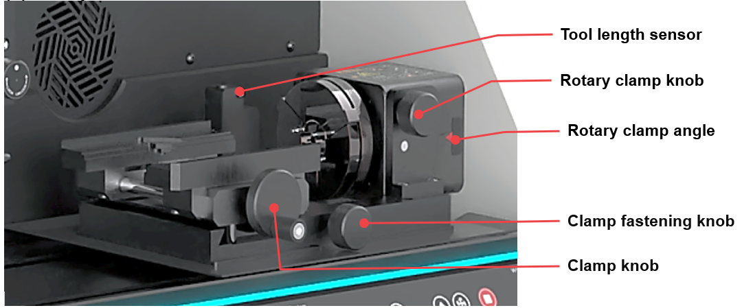
| Tool length sensor | Automatic tool length measurement sensor. |
| Rotary clamp knob | Knob for securing the rotary clamp at the desired angle. |
| Rotary clamp angle | Angle scale for the rotary clamp. |
| Clamp fastening knob | Knob for securing the clamp. |
| Clamp knob | Knob for fastening the material to the clamp. |
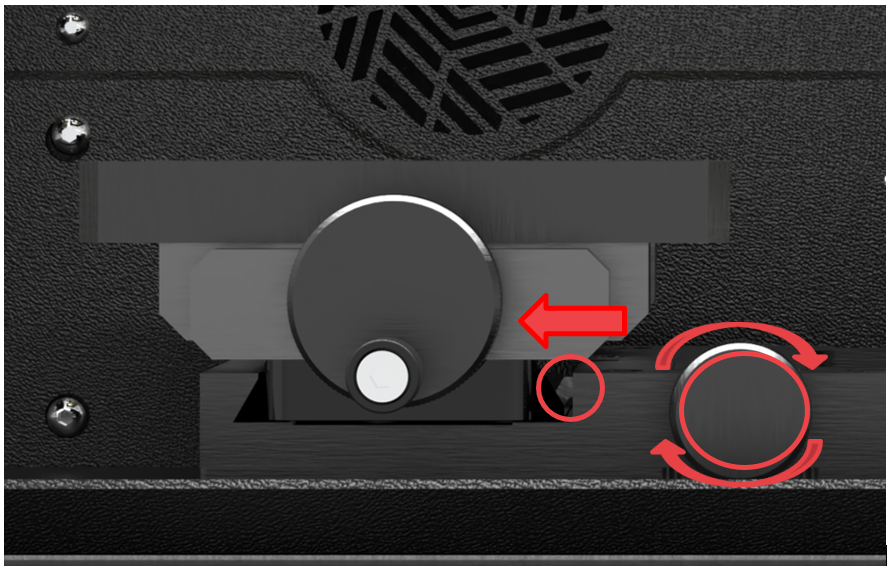
To secure the clamp, turn the clamp fastening knob. Turn it clockwise to secure, and counterclockwise to release.
Rotating the clamp fastening knob extends the push rod to the left, securing the clamp.
¶ 1) Multipurpose Clamp
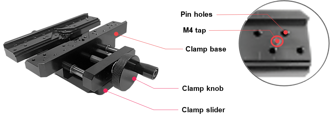
This single clamp alone makes engraving on various materials possible without the use of any additional clamps.
¶ How to secure the material in place
Use the clamp knob to hold the material in place. Turn the clamp knob clockwise to fasten the clamp, and counterclockwise to loosen or widen it.
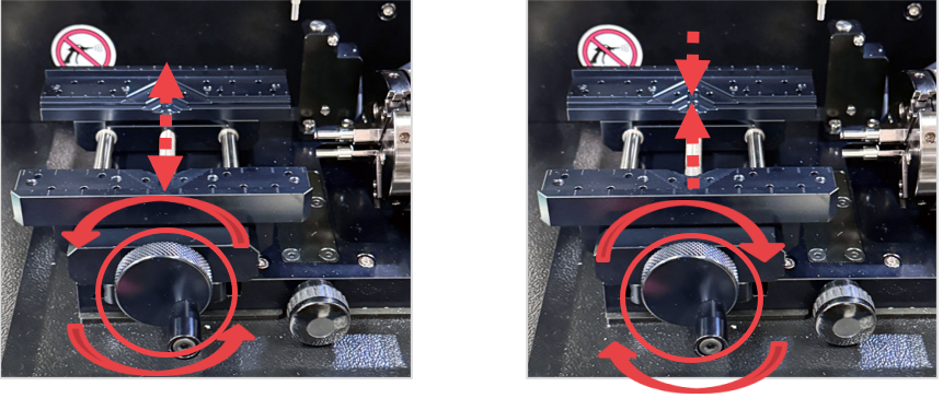
Marks may be left on the material if fastened tightly.
¶ How to position the material
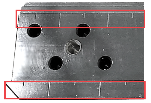
Use the vertical ruler bar as an alignment guide to help you position and align your material to the clamp with ease and accuracy. Properly place your material on the clamp then check the alignment.
- 1. Watch adapter CP-84
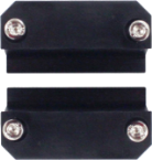
- 2. Bracelet adapter CP-85
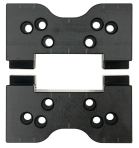
- 3. Bar necklace adapter CP-166
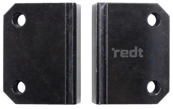
- 4. Brick adapter CP-167, 167S
- 5. Curved tag adapter CP-182
¶ 2) Rotary Clamp
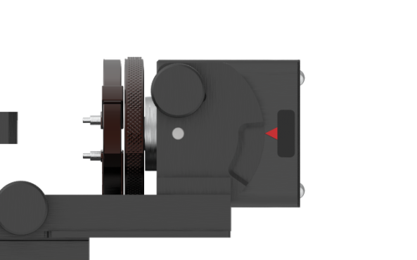
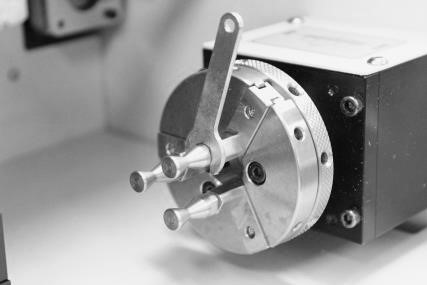
The built-in rotary clamp is used for engraving both the inside and outside of rings.
※ When marking on the inside of a ring, marking beyond the angle of 30° may not be possible.
¶ How to activate ring engraving mode
Press the rotary clamp button to activate ring inside/outside engraving mode.
| Mode | ||
|---|---|---|
 |
CNC Mode | From left to right [Cancel, CNC Flat, CNC ring outer diameter, CNC ring inner Diameter] modes.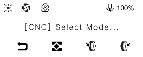 |
 |
Laser Mode | From left to right Cancel, Laser Flat, Laser Rotary  |
¶ How to secure the ring in place
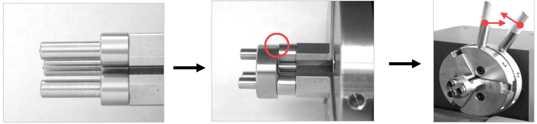
- When engraving the outside
Place the ring onto the finger chucks. Rotate the rotary clamp to outward-inward directions to lock and secure the ring in place. Make sure that the ring is firmly attached and locked so it won’t fall off or spin during operation.
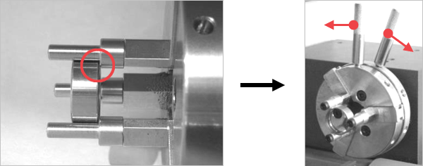
- When engraving the inside
Insert the ring in between the finger chucks. Rotate the rotary clamp to inward-outward directions to lock and secure the ring in place. Make sure that the ring is firmly attached and locked so it won’t fall off or spin during operation.
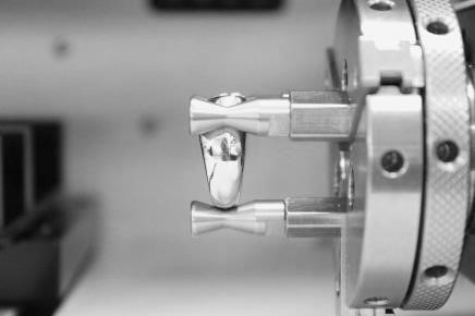
If the thickness of ring is not even, mix different sized chuck fingers to hold it.
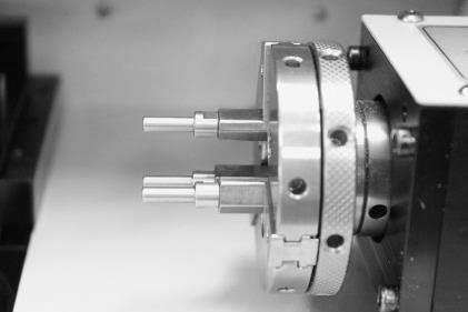
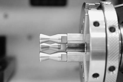
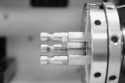
¶ Finger Chuck Types
There are three types of finger chucks available to match the shape and size of the ring.
 |
 |
 |
| Flat chuck finger | Round chuck finger (wide) | Round chuck finger (narrow) |
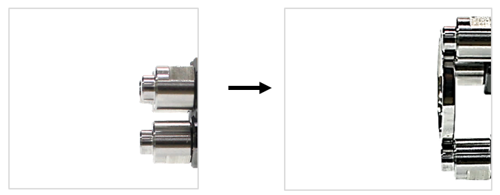
¶ How to secure a thin ring when marking the inside
When marking on thin rings, first, replace the finger chuck to 2mm with a finger chuck spanner. Then, insert the ring into the finger chuck. Last, fasten the ring with the finger chuck handle. To widen or tighten the gap of the finger chuck, use the finger chuck handle.
¶ How to replace finger chucks
Choose the appropriate finger chucks for your ring. Insert the finger chucks into the holes then fasten them tightly with the use of a finger chuck spanner.
※The finger chuck spanner is included in the package.
¶ 3) Cutting Clamp
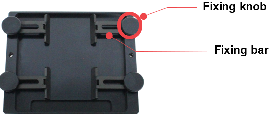
1. Place the material on the cutting clamp. Secure the material to the cutting clamp by using the fixing knobs then fasten the fixing knobs with the fixing bars.
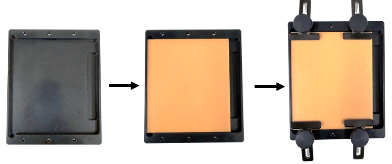
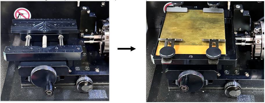
2. Fit the cutting clamp on the multipurpose clamp then secure it.
¶ 4) Flat Clamp
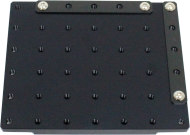
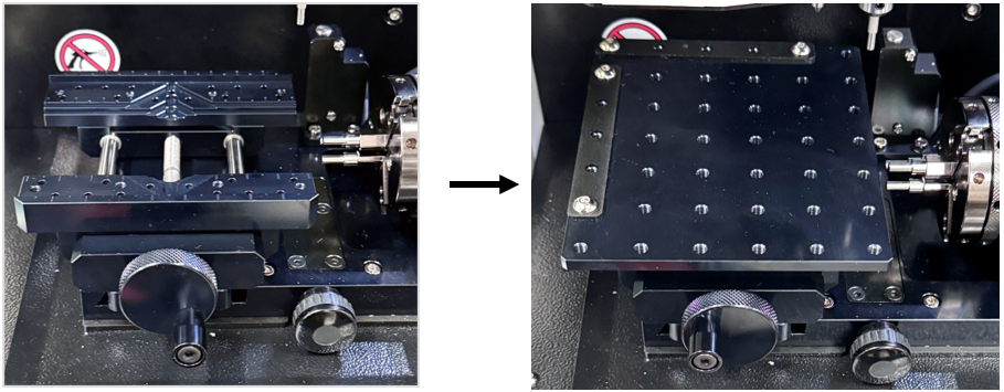
Flat clamp for repeatedly positioning nameplates and similar items in the same location during laser marking.
| L-wrench(3mm) (CP-L30) |
 |
1EA | For setting the focus pointer and fixing the flat clamp guide. |
1. Fit the flat clamp on the multipurpose clamp then secure it.
¶ 5) Anti-curling Clamp
※Anti-curling clamp is sold separately.
The anti-curling clamp is used to hold thin plates in place. It is used when laser cutting sheet materials.
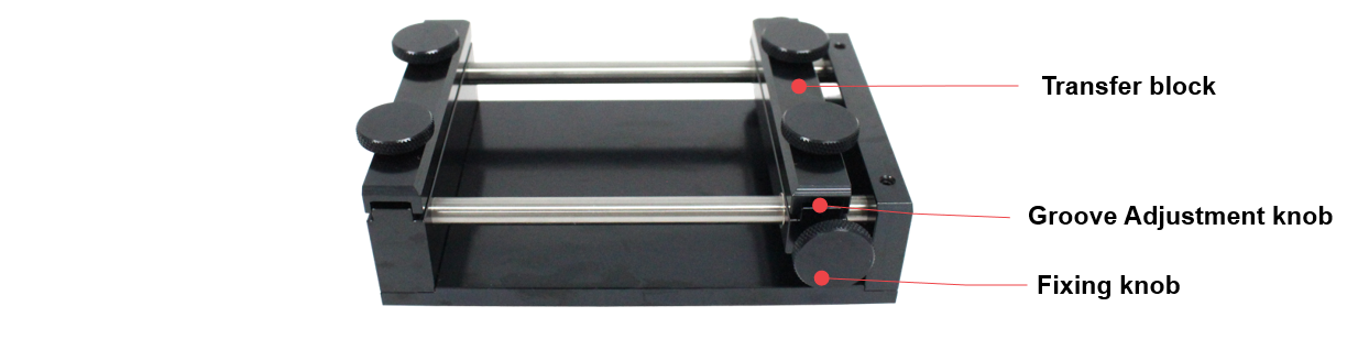
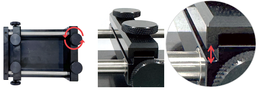
1. Set the position of the transfer block according to the size of the material, and secure it using the transfer block fixing knob.
2. Turn the fixing knob to widen the gap of the clamp.
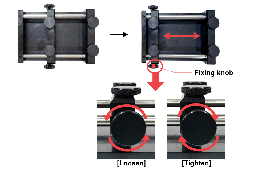
[Loosen] Releases the transfer block.
[Tighten] Adjusts the transfer block position and secures it.
3. Turn the groove adjustment knob to the left to loosen the groove of the clamp.
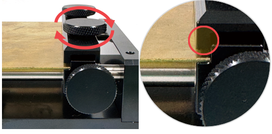
4. Place and secure the material to mark. Turn the groove adjustment knob to the right to fasten the groove of the clamp.
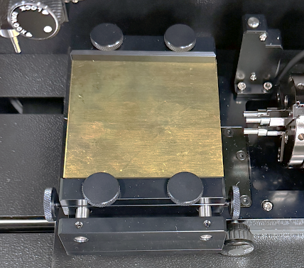
5. Before using the anti-curling clamp, remove the multipurpose clamp. Slide the anti-curling clamp along the X-axis to the desired position, then secure it using the clamp fastening knob.
¶ 6) Pen Jig
※Optional device; sold separately
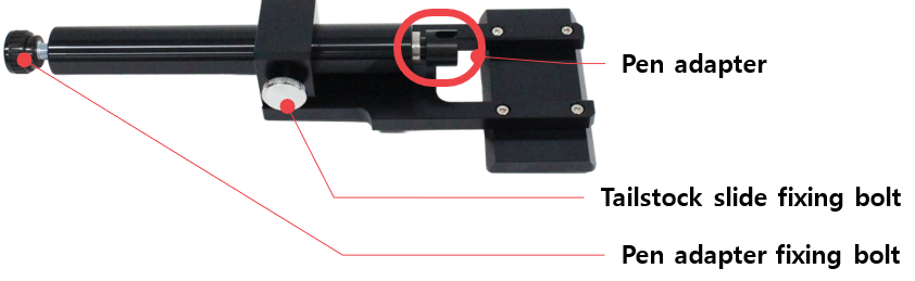
Pen jig is used to firmly hold cylindrical materials in place. It is specifically used to avoid objects with cylindrical shapes such as pen, tumbler and wine glasses to tilt to one side during engraving process.
¶ Before using the pen jig
Removing the tailstock hole cover allows for a greater adjustment range when securing the pen jig.
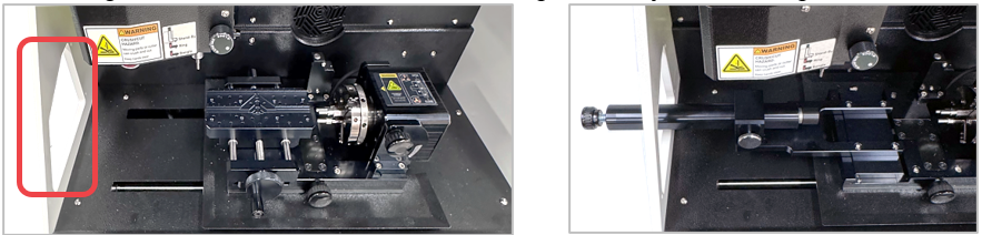
1. (With the multipurpose clamp removed) Secure the material in the flat chuck finger of the rotary clamp, then insert the pen jig.

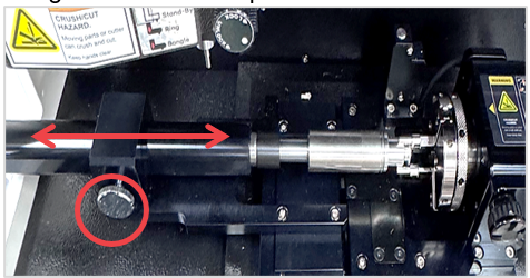
2. Adjust the tailstock until it contacts the material secured in the rotary clamp, then tighten the tailstock slide fixing bolt to lock it in place.
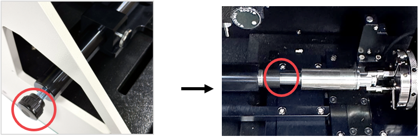
3. Turn the pen adapter fixing bolt to finely adjust the pen adapter and securely fix the material.
¶ Ring Adapter
※Optional device; sold separately.
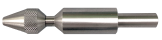
Ring adapter is used to secure the ring when engraving the outside of the ring. It is attached to the tailstock and the rotary clamp to firmly hold the ring in place during engraving process.
| Ring adapter (CP-241) |
|
1EA | For jig: To firmly hold rings in place when engraving the outside. |
| Collet for rings |  |
1SET | For size expansion: 9 types of collets are provided for different ring sizes. |
¶ How to set up the ring adapter
1. Turn the fixing nut counterclockwise to detach the ring adaptor.
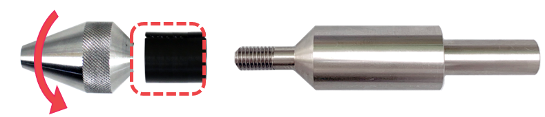
2. Insert the ring into the collet to match the size.
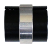
There are nine types of (expandable) collets available for different ring sizes.
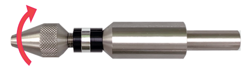
3. Attach and secure the collet into the ring adapter by turning the fixing nut clockwise.
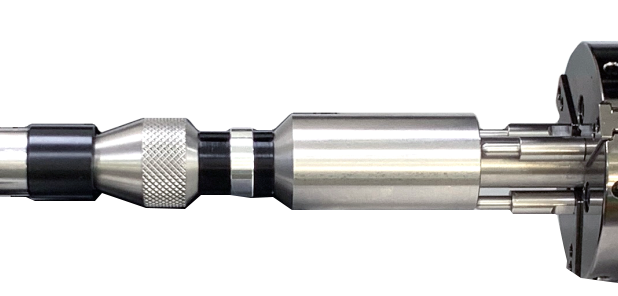
4. Loosen the chuck fingers by turning the rotary clamp then insert the ring adapter.
¶ 4. Keypad

| Display | Status display | ||
| Operation Buttons | Activate the operations intended to perform | ||
 |
Direction Key (X,Y/A) |
Engraving area adjustment  (X) Moves X axis (X) Moves X axis  (Y)(A) Moves Y/A axis (Y)(A) Moves Y/A axis ※Y-axis movement in flat mode, A-axis movement in rotary mode |
|
 |
 |
Direction Key (Z) | Moves Z axis up and down |
 |
Vacuum ON/OFF | Chip collector power button • Automatic control: The device starts automatically once the engraving operation begins and stops automatically once the engraving operation is completed. • Manual operation: Automatic control is deactivated if the device is manually switched on. Once the engraving operation is completed, the device should be manually turned off. ※ We strictly advise our users to use the Chip collector during engraving operation for safety. The Chip collector prevents exposure form harmful inhalable particles and debris like metal chips and dusts which may cause eye injury if they get stuck in the eye or respiratory problems if inhaled. |
|
 |
Menu | Enter the menu mode | |
 |
Start | Start marking button • Start marking: Long-press (for 2 seconds) the [START] button to start marking. • Repeat marking: Press the [START] button to finish marking, then double-press (tap twice) the [START] button to repeat marking. • Menu: Press OK when using the menu. |
|
 |
Stop | Stops/cancels marking | |
¶ 5. Menu
To enter Menu mode, press [Menu] button. Select a menu item using the ◀ and ▶ buttons then press [Start] button to enter the menu item.
| 1. Tool Change | Changes the tool. | |
| 2. Spindle Setup | Set spindle functions. -Spindle rotation speed: 50 to 100% (10% increments adjusted) -Start/stop spindle rotation |
|
| 3. Calibration | 1. Touch Sensor | Adjusts touch sensor settings. |
| 2. Probe | Adjusts probe settings. | |
| 4. Ring Inside Area Check | Sets a method for checking the inner diameter engraving area: 1. L-tool 2. Laser pointer |
|
| 5. Chuck Revolution | Rotates the rotary chuck. | |
| 6. Adjust Brightness | 1. Status LED | Adjusts status LED brightness |
| 2. Pointer | Adjusts focus laser pointer brightness | |
| 7. Vacuum Setup | Sets the Chip collector function. - Set to automatic control. - Removes the chip collector type setting. |
|
| 8. Tool-Pos Recording | Records your current location; set whether to activate or not. | |
| 9. Language | Selects language. | |
¶ 6. Display
The display shows the status, functions, mode, and check messages. Icons are displayed differently depending on the selected function. The four buttons at the bottom represent different functions and each function vary depending on the selected mode.
¶ 1) Standby-Flat
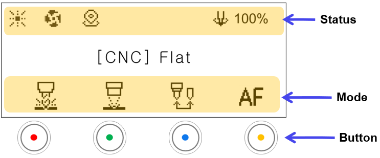
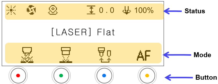

| Status | ||
|---|---|---|
 |
Focus pointer | Laser pointer ON/OFF |
 |
Chip collector power | Chip collector ON/OFF: Icon does not appear when OFF |
 |
Send current position | Sends the current position coordinates. Not displayed when set to OFF. |
 |
Z-axis position | Z-axis Position: Material height |
 |
Spindle rotation speed | Displays the spindle rotation speed as a percentage (%). |
| Mode | ||
|---|---|---|
|
CNC Mode | From left to right [Cancel, CNC Flat, CNC ring outer diameter, CNC ring inner Diameter] modes.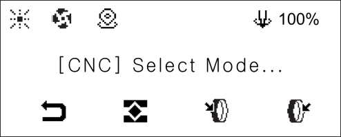 |
|
Laser Mode | From left to right Cancel, Laser Flat, Laser Rotary  |
 |
Tool change | Switches to tool change mode |
 |
Auto focus | Measures the material height and moves to the focus position. In CNC mode, the height is measured at the current tool position. In laser mode, the height is measured at the center position of the clamp. |
¶ 2) Standby–Rotary
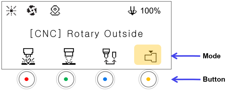
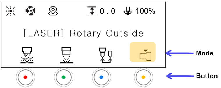

| Mode | ||
|---|---|---|
 |
Finger Mode | [Program connection required.] The mode changes in sequence (Flat finger → Round finger → cylinder) in a loop whenever the button is clicked. Flat Finger Round Finger Round Finger Cylinder (Used for cylinder engraving / ring cutting) Cylinder (Used for cylinder engraving / ring cutting) |
¶ 3) Move Mode
Press one of the ◀▶▼▲ buttons in the [STANDBY] mode to activate [MOVE].
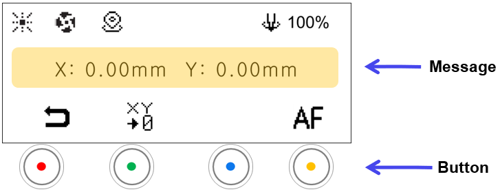
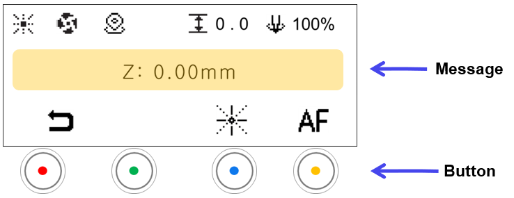

| Message | |
|---|---|
| Position | Display current position coordinates. |
| Mode | ||
|---|---|---|
 |
Standby Mode | • Switches to the STANDBY mode • Switches automatically to [STANDBY] mode if not in use for 10 seconds. Press any buttons to activate [MOVE] mode. |
 |
Save Origin | [Displayed only in CNC mode.] Saves the current position as the XY origin *Short-press: Temporary save *Long-press: Permanent save |
|
Focus Pointer | [Displayed only in laser mode.] Brightness levels There are 4 levels of brightness control. Each time the button is pressed, the level changes as well as the level cycles. 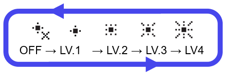 |
|
Auto focus | [Displayed only in CNC/Laser Flat modes. Measures the material height and moves to the focus position. In CNC mode, the height is measured at the current tool position. In laser mode, the height is measured at the center position of the clamp. |
¶ 4) Check rotary clamp marking area
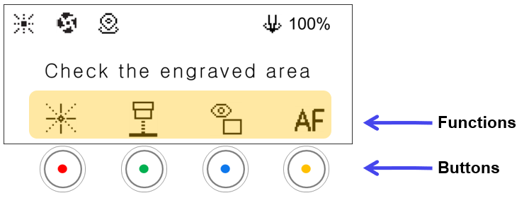
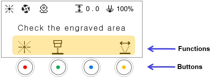

| Mode | ||
|---|---|---|
|
Focus Pointer | [Displayed only in laser mode.] Brightness levels There are 4 levels of brightness control. Each time the button is pressed, the level changes as well as the level cycles. |
 |
Head Pointer | Turns the scan head center pointer ON/OFF. |
 |
Preview Toggle | [Displayed only in flat mode.] Switches the preview between a rectangle and an outline. |
|
Auto Focus | [Displayed only in flat mode.] Measures the material height and moves to the focus position. The height is measured at the center position of the current work area. |
 |
Left/Right Area Movement Mode | [Displayed in rotary mode.] Changes the left/right area movement mode. Toggles between Work Area ↔ Vise.  |
¶ 5) Engraving mode-CNC
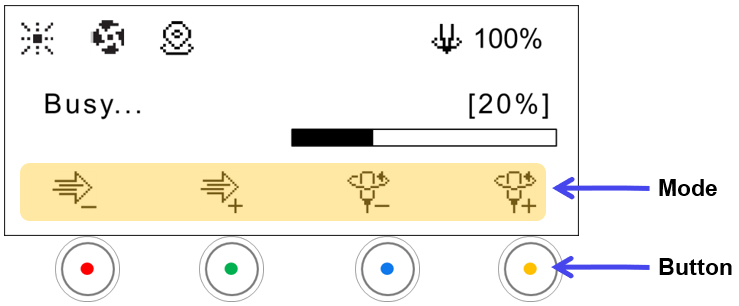
 |
Engraving Speed Control | Reduces engraving speed by 1mm/s whenever the button is pressed. |
 |
Increases engraving speed by 1mm/s whenever the button is pressed. | |
 |
Spindle Speed Control | Reduces spindle speed by 10% whenever the button is pressed. |
 |
Increases spindle speed by 10% whenever the button is pressed. |
¶ 6) Engraving mode-Laser
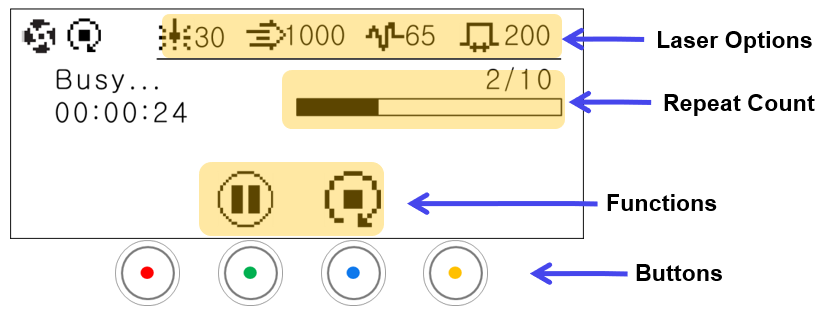
| Status Display | ||
|---|---|---|
 |
Stop after current operation | The marking does not stop immediately; it stops after completing the marking in progress. |
| laser Options | ||
|---|---|---|
 |
Power | Displays set laser power value |
 |
Speed | Displays set laser speed value |
 |
Frequency | Displays set laser frequency value |
 |
Pulse width | Displays set laser pulse width value |
| Time left | The remaining time until marking completion is displayed. ※Calculate the time required for the 1st cycle. |
| Repeat Count | When setting a repeat count, the number of repeats is displayed. (Example: 2/10 → performing 2 times out of a total 10 markings) |
| Functions | ||
|---|---|---|
 |
Pause | Pause the operation in progress  |
|
Stop after current operation | End repeated marking in progress. The marking does not stop immediately; it stops after completing the marking in progress. |
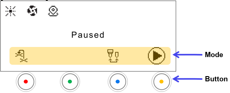
¶ 7) Pause-CNC
| Mode | ||
|---|---|---|
 |
Return back to Previous position | Returns back to the previous position and resumes engraving. |
|
Tool Change | Switches to tool change mode |
 |
Resume | Resumes engraving. |
¶ 7. Status Indicator
The status LED is installed only on the top of the keypad and indicates the operating status of the device.
The machine displays flashing or blinking lights to show its current status. The lights displayed indicate the following status:
| Status | Blinking Interval |
| Waiting |  |
| Engraving | |
| Operating |  |
| Notification |  |
| Error |  |
Press [Menu] button to enter menu mode.
Select [6. Adjust Brightness] then press ▶ button.
| 6. Adjust Brightness | 1. Status LED | Adjusts status LED brightness |
| 2. Pointer | Adjusts focus laser pointer brightness |
Select [1. Status LED] then press [Start] button.
Adjust the brightness using the ◀▶ (Direction X) buttons.