¶ Contents
- 1. Touch Sensor (Tool Calibration)
- 2. Probe Calibration
- 3. Laser focus calibration
- 4. Guide laser calibration
- 5. Correction
- 6. Focus pointer
- 7. Rotary origin
- 8. Flat origin
- 9. Rotary Clamp Origin point (Z axis)
- 10. Tool-laser center
- 11. Camera
- 12. Manual calibration
- 13. Import calibration
※ The machine is initially set up at the factory. Please contact your reseller first before making any changes to the settings of the machine.
※ (CNC) Only carbide and diamond tools can be calibrated. Do not calibrate tools such as endmill and cutter.
※ (CNC) Be sure to unlock the pressure lock when calibrating the machine. Nose, tool and material can be damaged if the head is fixed or when the pressure lock is locked.
※ Calibrate the machine in the following order:
Tool calibration → Probe calibration → Laser focus calibration → Guide laser calibration → Correction → Focus pointer → Rotary clamp origin point → Tool–laser center calibration → Camera calibration.
※Use appropriate material for calibration. The machine’s warranty service does not cover mishandling of the machine resulting in damage or failure.
※ RECOMMENDED: Use a black anodized aluminum material.
※ A separate program for Setup Machine is provided. Run the program first to calibrate the machine.**
¶ 1. Touch Sensor (Tool Calibration)
1. Place and secure the material on the clamp.
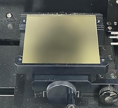
2. When attaching the tool, keep the length short as possible.
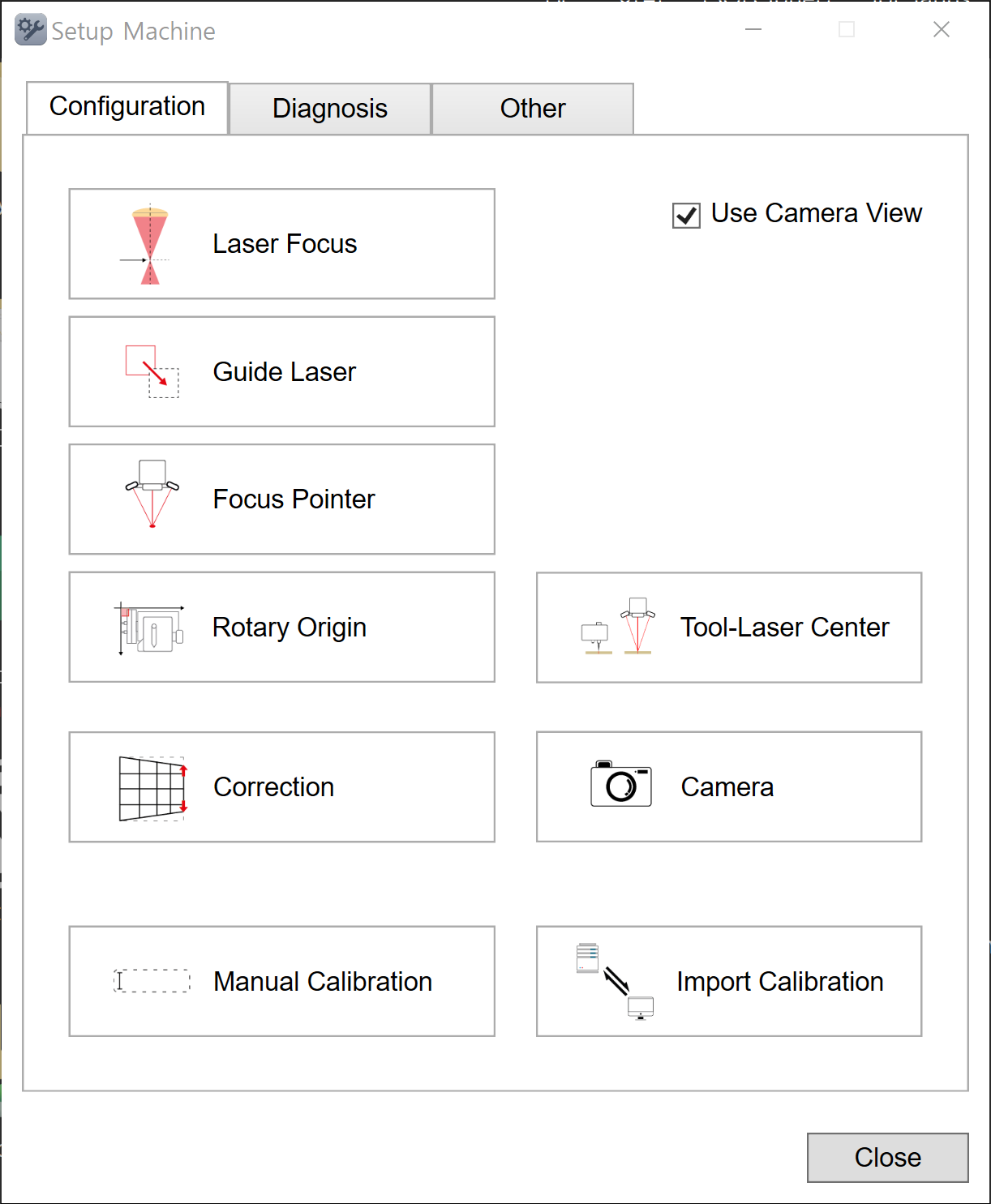
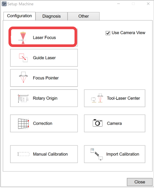
3. Click [Laser Focus].
4. Click [Touch sensor].
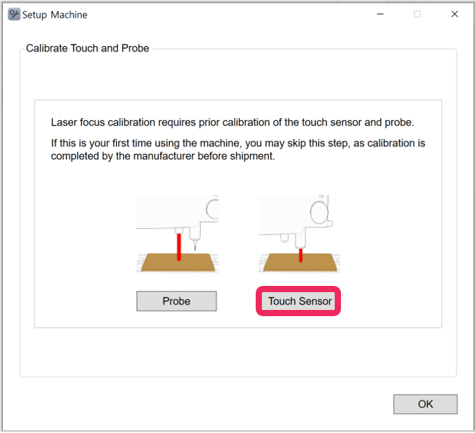
5. The tool will be lowered and come in contact with the material and will be placed in the center of the clamp.
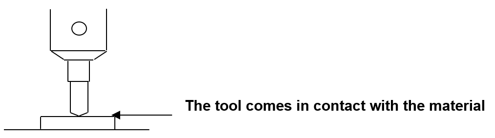
6. Lower the tool by using 
 buttons or loosening the fixing bolt of the tool with a wrench, or lift the material with your hand to make the tool and material come in contact as shown in the picture below.
7. Long-press and hold  button (for more than 3 seconds) until it beeps to confirm that the setting is saved then the tool will measure the material’s height.
¶ 2. Probe Calibration
1. Place and secure the material on the clamp.
2. Click [Laser Focus].
3. Click [Probe].
.png)
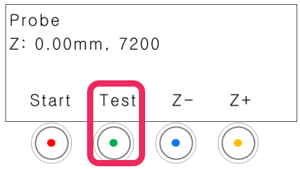
4. When “Probe” appears on the LCD window (as shown below), press [Start] button on the LCD window, then press button to lower the tool until it comes in contact to the material. Loosen the tool fixing bolt with a wrench to lower the tool or lift the material with your hand to make the tool and material come in contact.
5. Long-press and hold button (for more than 2 seconds) until it beeps to confirm that the setting is saved. The probe will then measure the material then the machine will measure the tool.
6. Press [Check] button to start a test run. Check whether the tool draws four lines on the materials or not. If two lines out of four lines are shown on the material, then it is correct. If three lines are shown, press Z+ ( ) button to raise it by 0.05mm, and if one line is shown, press Z- (
 ) button to lower it by 0.05mm
(※0.05mm per line.)
7. Long-press and hold button (for more than 3 seconds) until it beeps to confirm that the setting is saved.
¶ 3. Laser focus calibration
Match the laser focus to the height of the material to increase accuracy when marking.
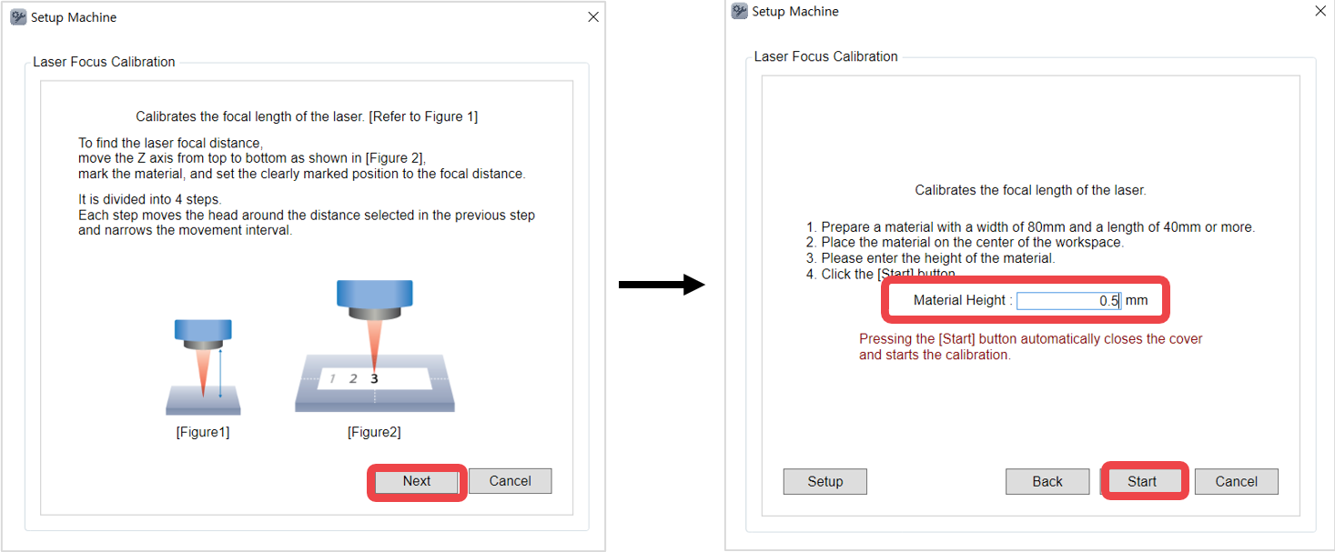
There are four stages involved when calibrating the laser focus. On each stage, the head moves according to the distance specified in the previous stage and the movement interval shortens.
[How to calibrate laser focus]
1. Place the material on the work area. Prepare material that is at least 80 mm (3.15 in) wide and 40 mm (1.57 in) tall.
2. Click [Laser Focus].
3. Click [OK].
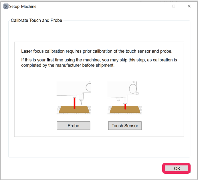
4. Read the notification displayed on the screen then click [Next]. Read the instructions that will appear on the screen then enter the height of the material.
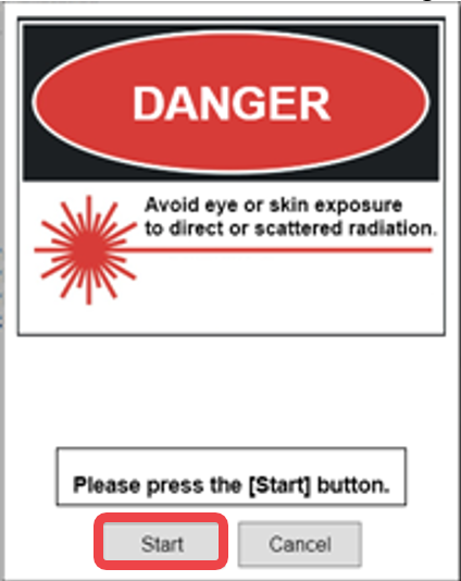
5. Be sure to read the warning notice first before clicking [Start].
6. The numbers and circles are engraved on the material with a laser.
Numbers 01~10 are engraved, and the numbers may vary depending on the laser focus.
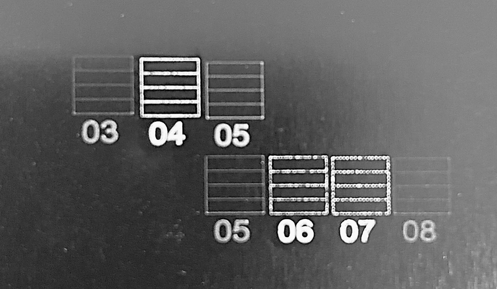
7. In [Setup Machine] window, enter the median number among the engraved numbers then click [OK].
For example, if the engraved numbers are 01, 02, 03, 04, 05, 06, 07, 08, 09, 10 enter the median number ‘05’ (or the number in the middle) then click [OK].
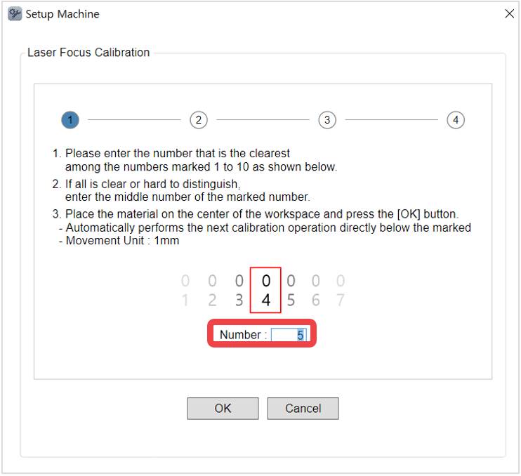
8. Repeat [step 5] and [step 6] four times to complete laser focus calibration with optimized option.
¶ 4. Guide laser calibration
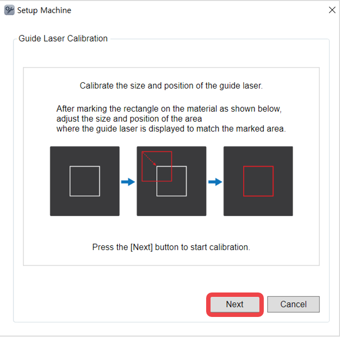
Calibrate the size and position of a guide laser.
¶ How to calibrate guide laser
1. Place the material on the work area. ※ Please use metal materials.
2. Click [Guide Laser].
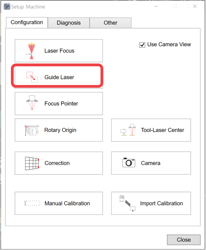
3. Read the notification then click [Next].
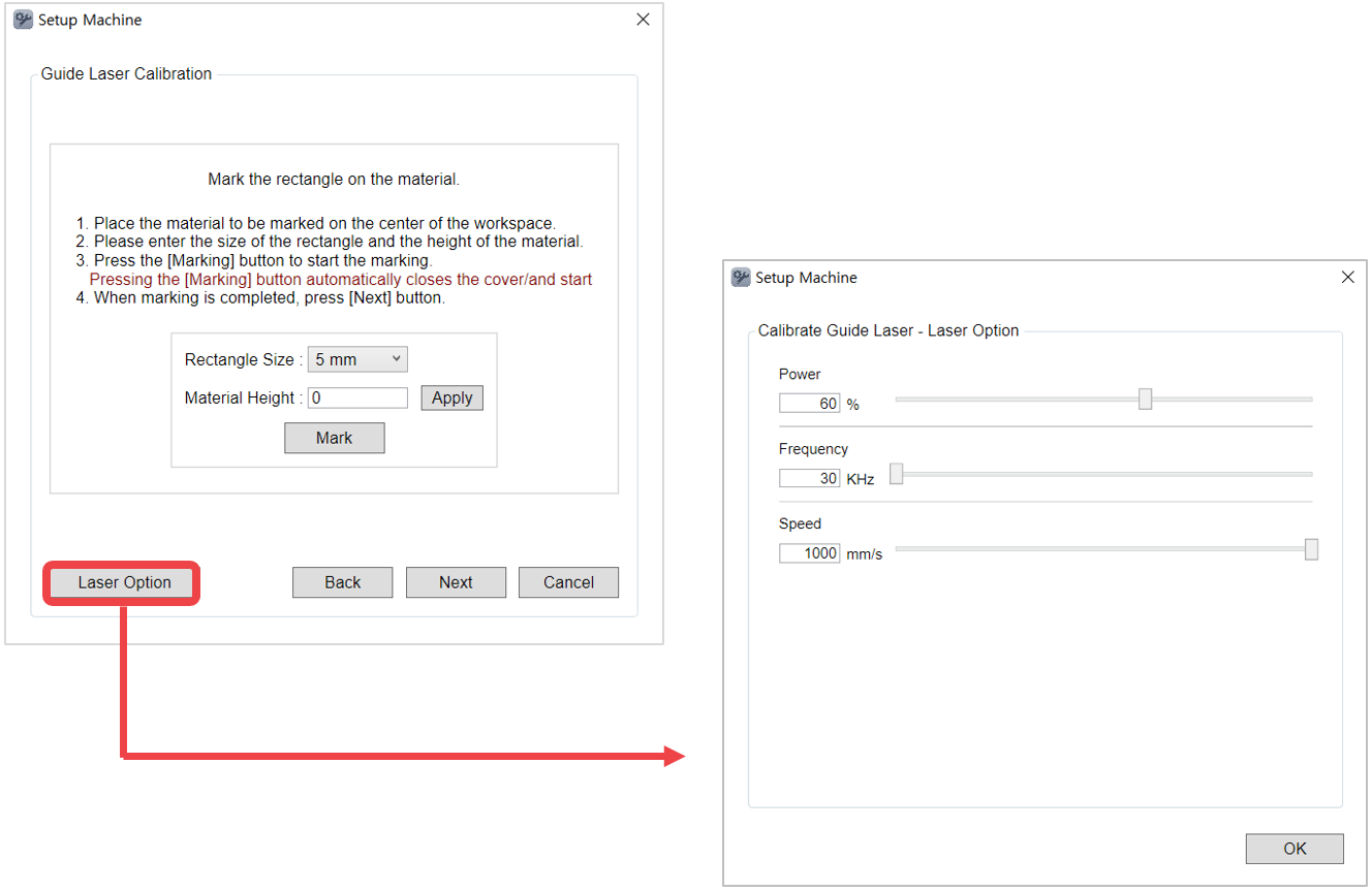
4. Select the rectangle size, then enter the material height. Click [Apply] to set the height, and then click [Mark]. After clicking the [Mark] button, manually close the machine cover. The rectangle will then be marked on the material.
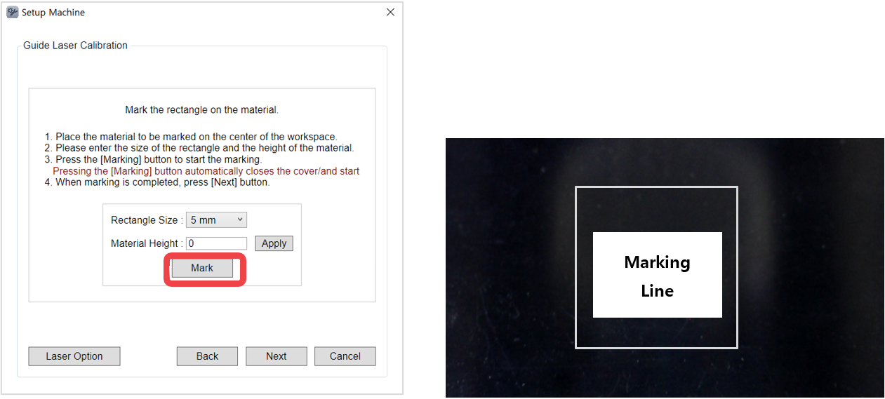
*A 20mm rectangle is marked on the material at a 0.5mm height.
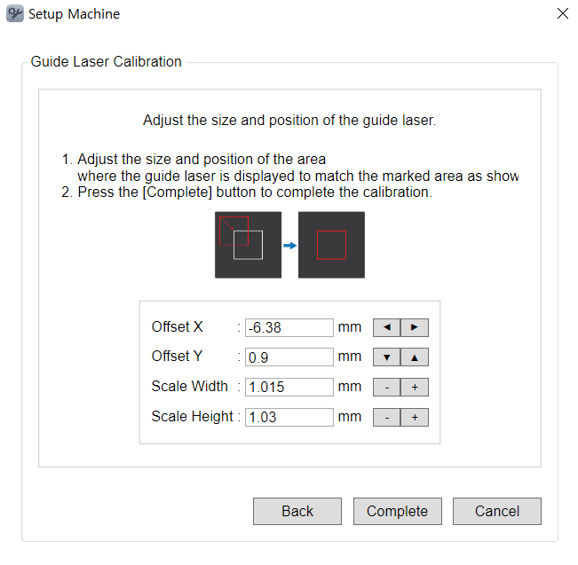
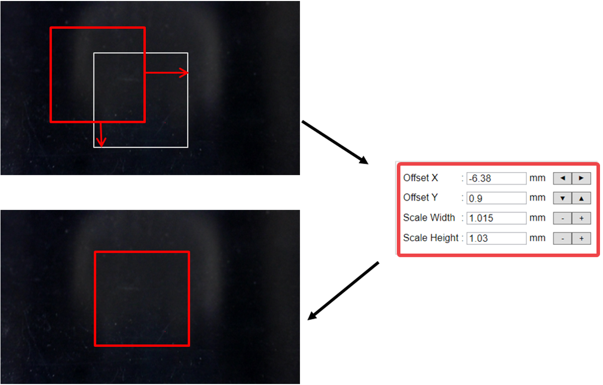
5. Once the guide laser appears at the end of marking, adjust the offset values, width and height to fit in the rectangle in [2. Parameter Setting] then click [Apply].
※Select [Laser Option] in the [Guide Laser Calibration] window to adjust the laser options.
¶ Advanced Guide Laser
1. In [Setup Machine] window, click [Other].
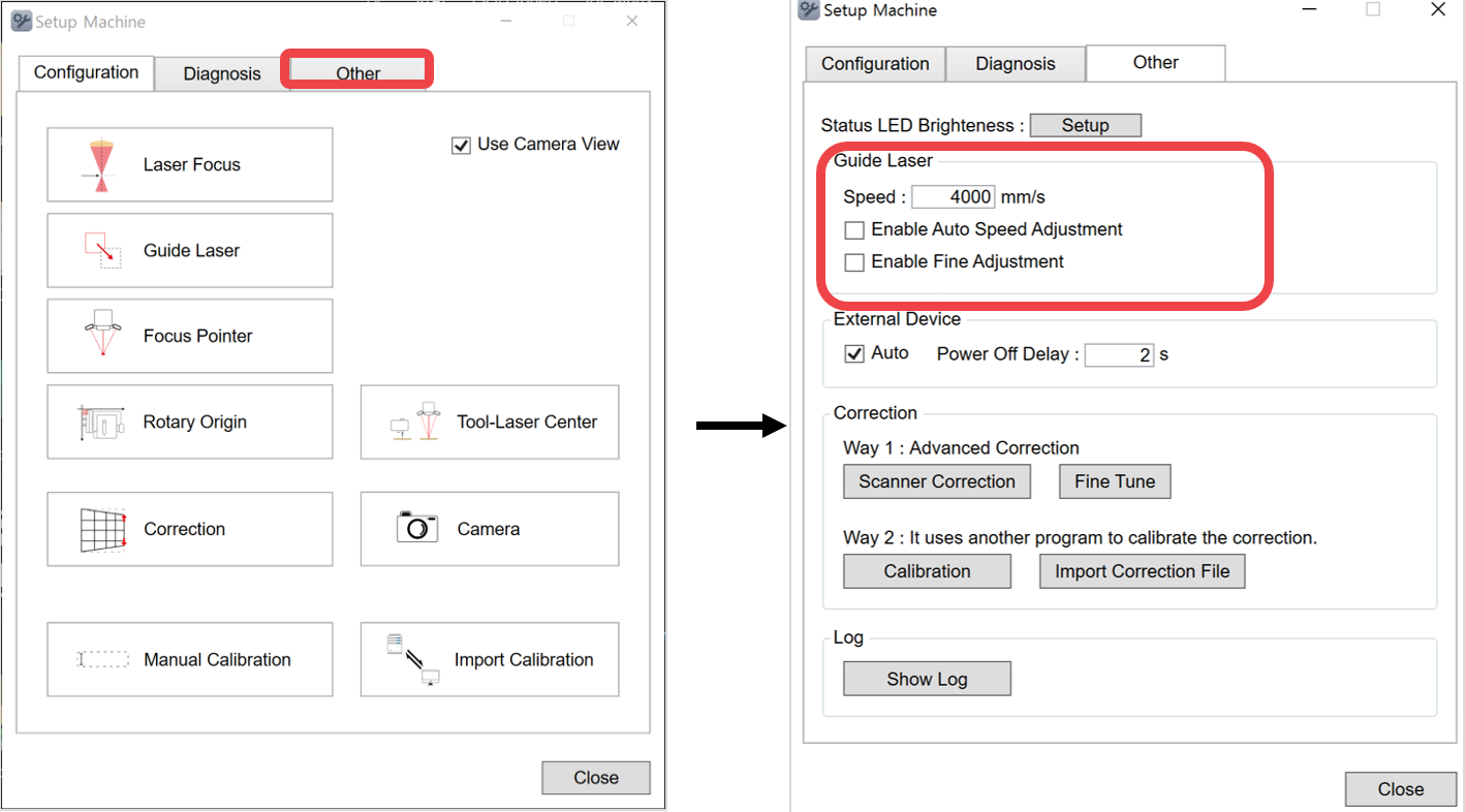
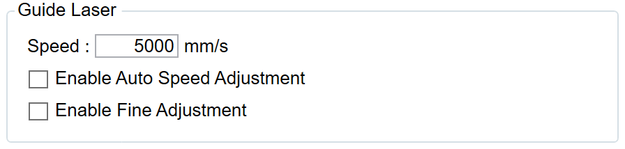
| Speed | Sets the guide laser speed |
| Enable Auto Speed Adjustment | Automatically adjusts the guide laser speed according to the size of the object to be marked when selected. |
| Enable Fine Adjustment | Automatically moves to the guide laser focus position (when checking the marking area) to enable precise marking area position when selected. ✽[Advanced Guide Laser] menu is added to the [Setup Machine] window when [Enable Fine Adjustment] function is selected and/or activated. ✽[Advanced Guide Laser] is required for calibration, and the calibration method similar to guide laser calibration method. 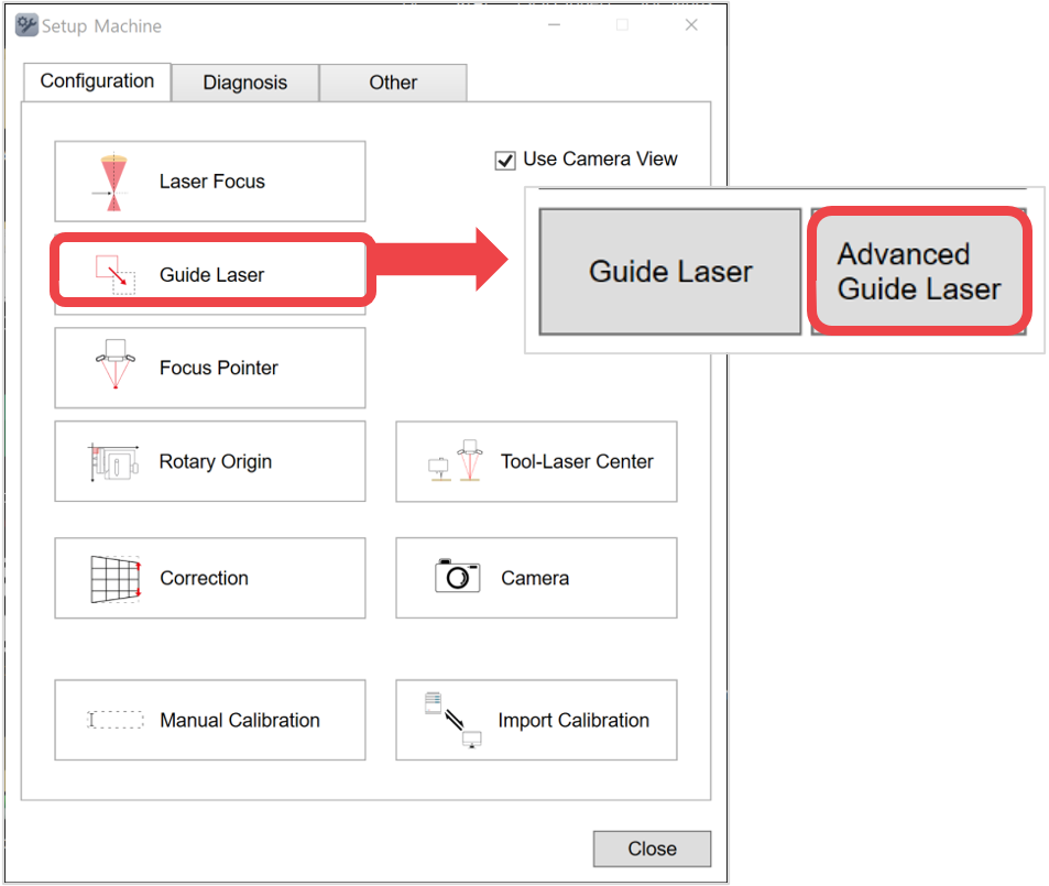 |
¶ 5. Correction
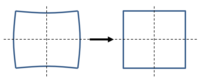
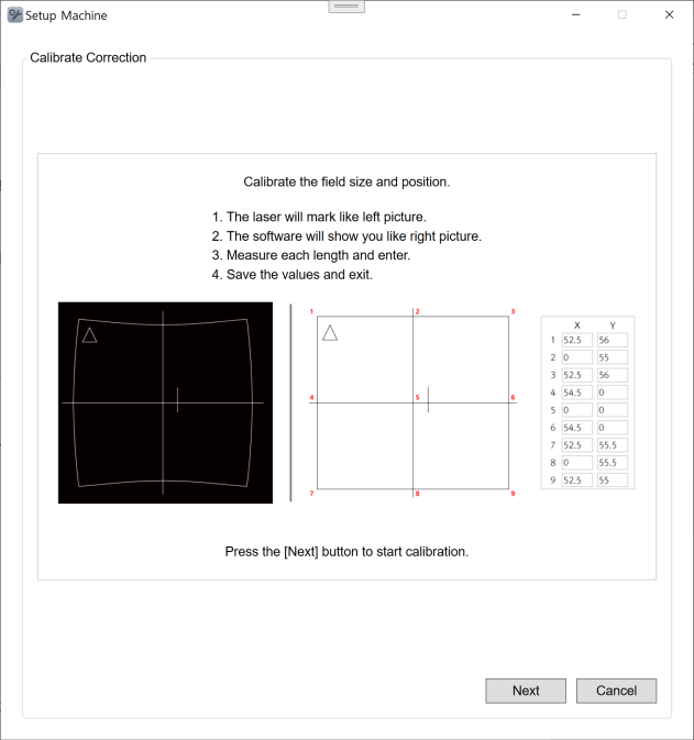
The father the laser moves away from the center, the greater the distortion occurs. When the laser passes through the lens after passing through the scan head, the farther it moves, the more distorted the shapes become (see figure on the left). To correct distortion, correction process is used (see figure on the right).
¶ How to calibrate correction
1. Use a material larger than (110x110 mm). Preferably, with a size of (120x120 mm).
2. Click [Correction].
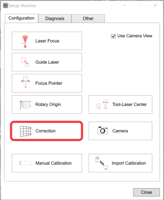
3. Read the notification on calibration process. Click [Next] to start calibration.
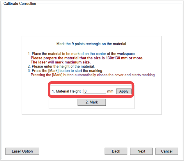
4. Enter the height of the material then click [Apply]. Click [Mark] to start marking.
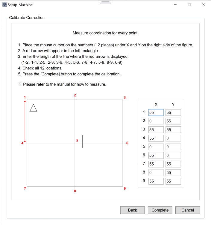
5. Measure the coordinate values in each corner. Enter the sizes then click [Complete] to finish calibration.
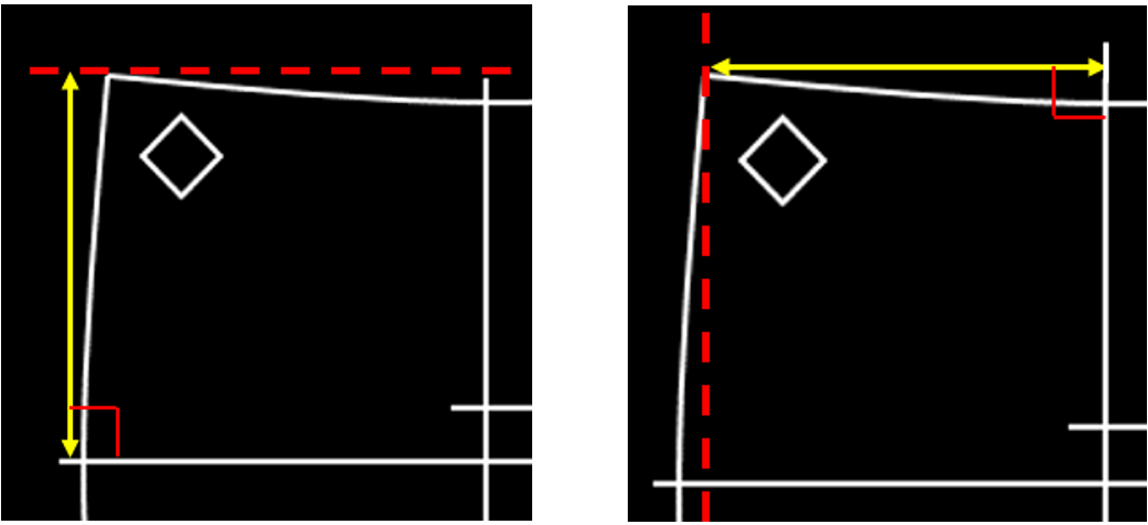
Be sure to measure the size from each corner (as shown below).
¶ 6. Focus pointer
Adjust the position of the head laser and V laser pointer.
| T-wrench(2mm) (CP-T20) |
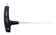 |
| L-wrench(3mm) (CP-L30) |
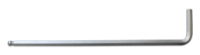 |
1. If a material is secured in the pendant clamp, remove it and fully tighten the clamp.
2. Click [Focus Pointer].
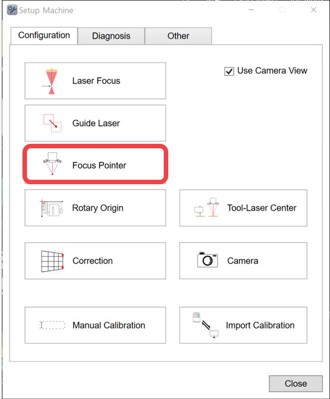
3. Position the head laser to the center of the work area. Use the direction key buttons to position it to the center. Then, click [Next].
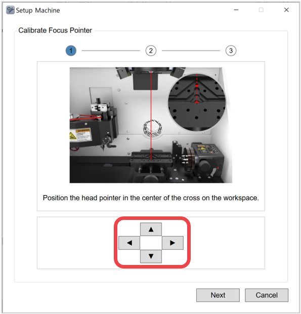
4. Place the flat material on the work area and enter the thickness. Then, click [Next].
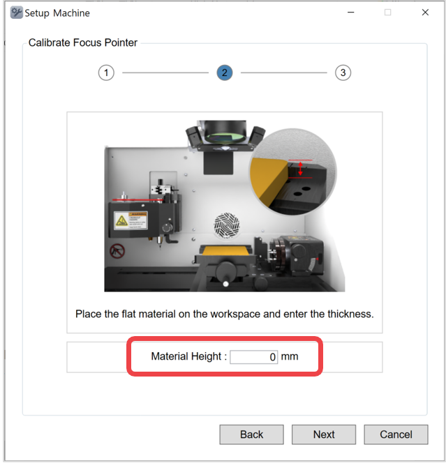
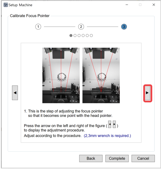
5. P Click ▶ button on the right to proceed in sequential order. ※Use a 2,3mm wrench. Take note that the setting process involves 4 steps. Be sure to proceed with both left and right pointers in the same process.
¶ 7. Rotary origin
1. Place and secure the rotary clamp to the work area.
2. Click [Rotary Origin].
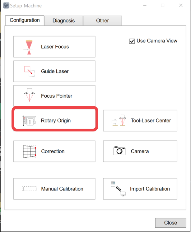
3. The process consists of two steps: setting the Y-axis origin and setting the X-axis origin.
4 [Y-axis origin setting] Secure a pointed tool in the rotary clamp as shown in the figure below.
| Setting tool | 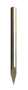 |
1EA | Tool for rotary origin setting. |
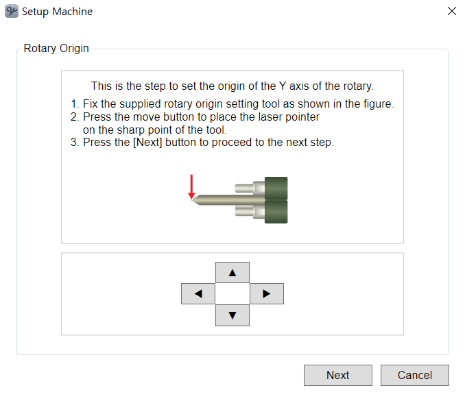
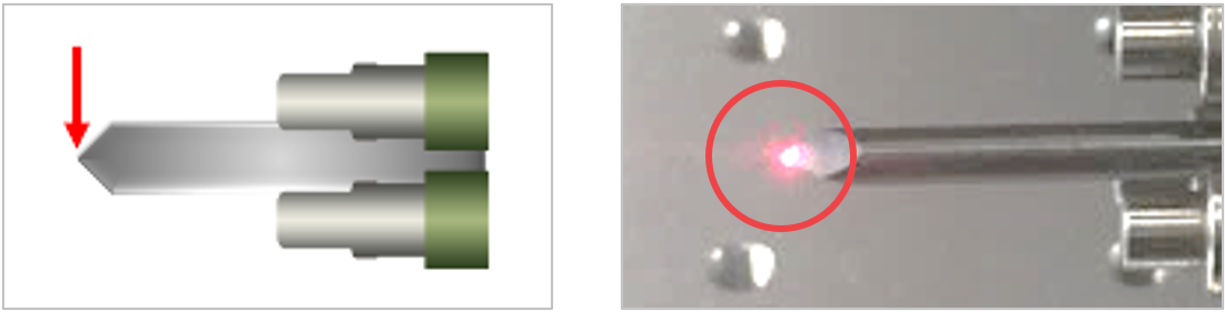
5. Match the tip of the tool to the laser pointer. Use the direction key buttons to position the laser pointer to tip of the tool. Then, click [Next].
Or, on the machine, use 
 buttons then long-press utton (for more than 1 second).
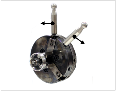
6. Remove the setting tool then insert the ring into the finger chuck (as shown below). Use both finger chuck handle to tighten the clamp and secure the ring.
7. [Proceed with X-axis Origin Setting] Secure the calibration material, enter the diameter and height, and press the [Apply] button.
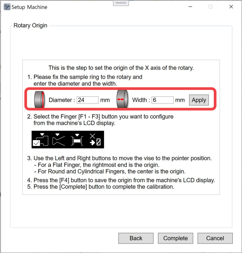
8. On the marking machine LCD screen, press the F1–F3 buttons to select the desired finger.
9. Press the Left/Right direction buttons on the marking machine to move the clamp and adjust the position.
• For the flat finger, the right end is the origin.
• For the round and cylinder fingers, the center is the origin.
10. Press the F4 button on the marking machine keypad to save the origin.
The origin must be saved for each finger individually.
¶ 8. Flat origin
You can set the origin in the Laser Options window.
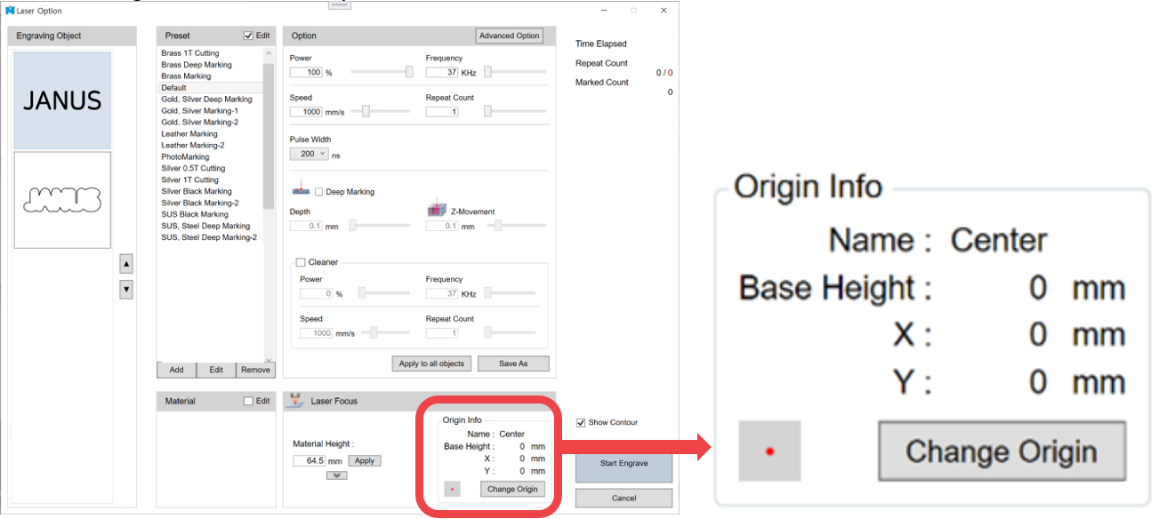
| Name | Sets the origin name. |
| Base Height | Sets the base height. For example, if the cutting clamp height is 30mm, entering 30mm as the Base Height sets the cutting clamp base as the focus reference. Therefore, entering 0mm for the Material Height moves the focus to the cutting clamp base. |
| Change Origin | Changes the selected origin. |
[Change Origin]
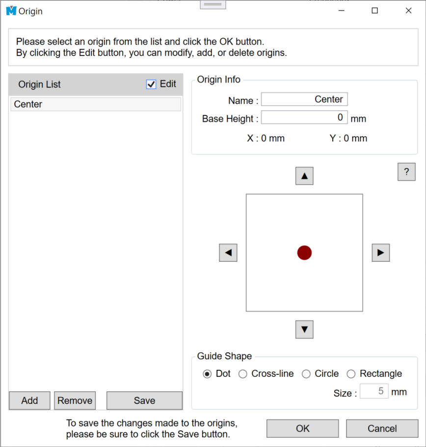
| Origin List | Displays the list of origins. You can add, delete, or edit origins. |
| Edit | You must select the Edit checkbox to activate the adjustment buttons for adding, deleting, or editing origins. |
1. To select and apply an origin, choose the desired origin from the Origin List and press the OK button.
To add or edit an origin:
2. Select an origin from the Origin List, enter the name and reference height, then adjust the origin position using the Up / Down / Left / Right buttons.
- When modifying an existing saved origin, you must press the Save button to apply and store the changes.
3. You can verify the origin position using the laser pointer.
The Guide Shape function allows you to check the origin position in various shapes.
- Dot: Displays the laser pointer as a dot.
- Cross-line: Displays a crosshair of the specified size.
- Circle: Displays a circle of the specified size.
- Rectangle: Displays a rectangle of the specified size.
- Size: Sets the size of the guide shape.
¶ 9. Rotary Clamp Origin point (Z axis)
1. To enter the [Ring Outside] mode, press [Finger Mode] button.
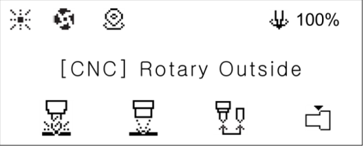
2. Set the sharp tool into the rotary chuck as shown below.

3. Press 
 button to switch to [Move mode-Rotary].
4. Use buttons to horizontally align the tip of the engraving tool to the tip of the blade (as shown below). Use buttons to adjust the distance between tools. Be sure the tips are closer to each other.
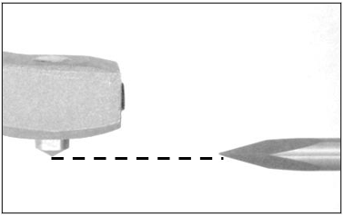
5. Press the  button to display save confirmation on the LCD window.
- Short press button: Temporary save (message guide X)
- Long-press and hold button (for more than 3 seconds): Permanent save
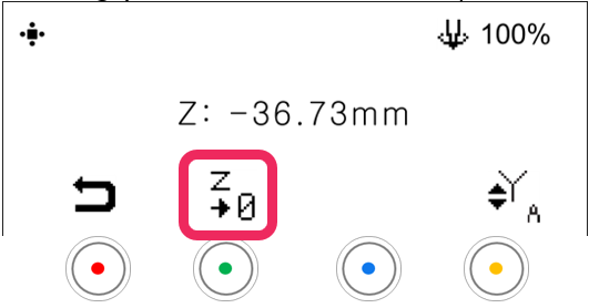
6. Press the button to save the setting.
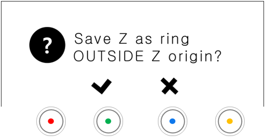
7. After tool measurement is completed, the Z origin for OUTSIDE is saved.
Repeat the same procedure to set the INSIDE.
¶ 10. Tool-laser center
Calibration used to align the engraving positions of the CNC tool and the laser
1. Secure the material in the work area. Prepare material that is at least 80 mm (3.15 in) wide and 40 mm (1.57 in) tall.
2. Click [Tool-laser Center].
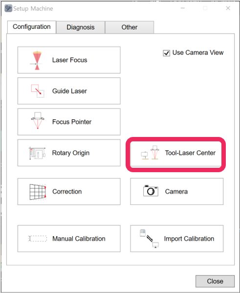
3. Select [Flat] or [Rotary]. Calibration must be performed for each mode.
• Flat: Enter the material height, then click [Apply].
• Rotary: Enter the material diameter and width, then click [Apply].
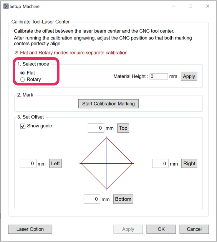
4. For Flat, secure a flat plate material or pendant.
For Rotary, secure a ring.
Click [Start Calibration Marking] to perform the calibration marking.
As shown in the figure below, the laser marks a diamond shape, and the CNC tool marks cross lines.
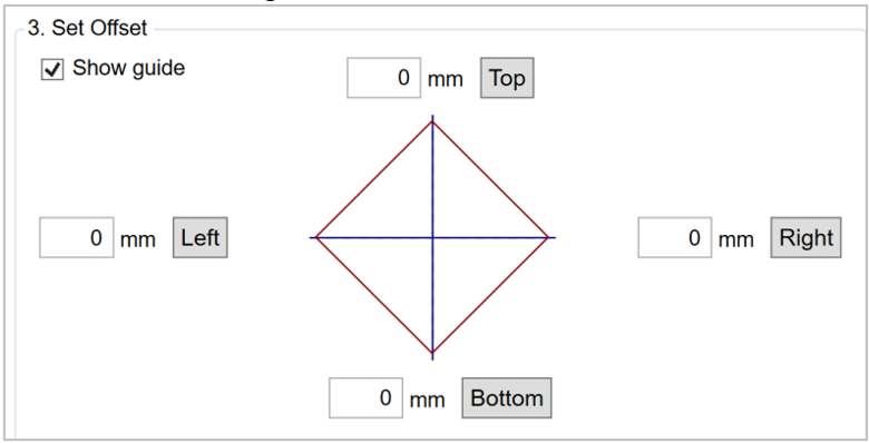
5. 5. Press the [Up/Bottom/Left/Right] buttons to adjust the offset.
This offset adjusts the CNC tool position, aligning it with the laser position.
After adjustment, click [Apply] to apply the value.
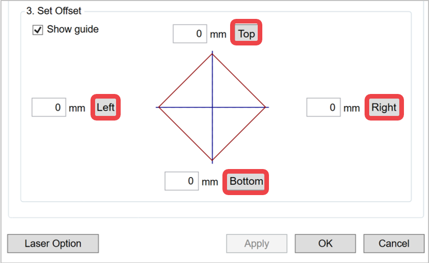
6. When calibration is complete, click [OK] to finish.
¶ 11. Camera
[Use camera view]
Select the checkbox (on the top right corner) to display Camera Viewer.
Use Camera Viewer to accurately check and calibrate each setting.
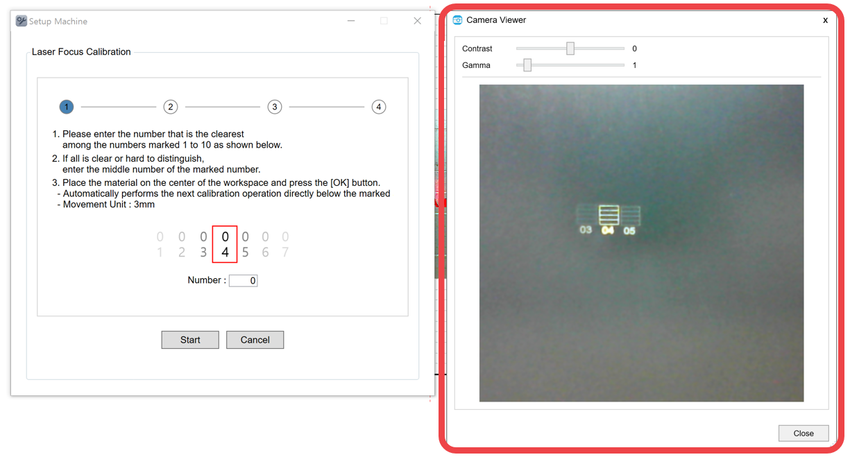
1. Place the material on the work area.
2. Click [Camera].
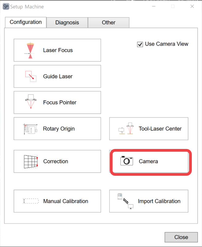
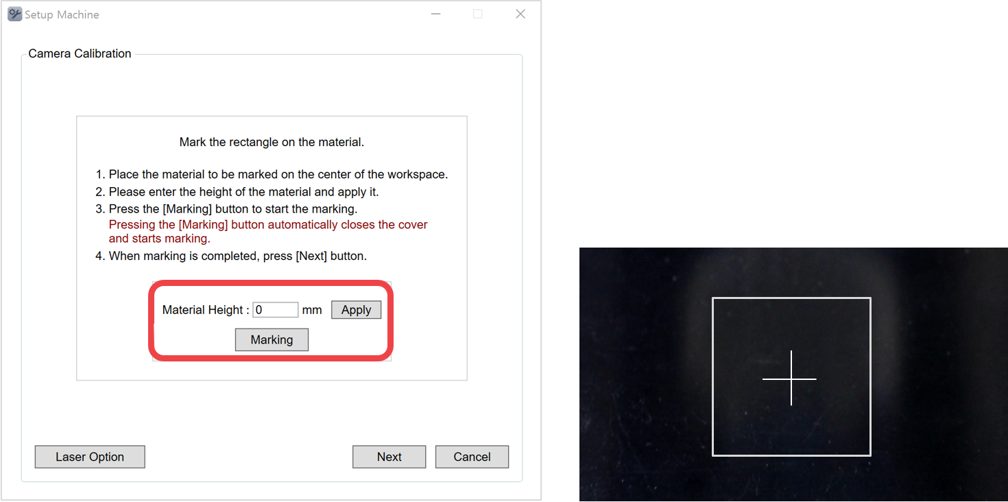
3. Enter the height of the material (to mark a rectangle), then click [Apply]. After clicking the [Mark] button, manually close the machine cover. An 80 × 80 mm rectangle will then be marked on the material.
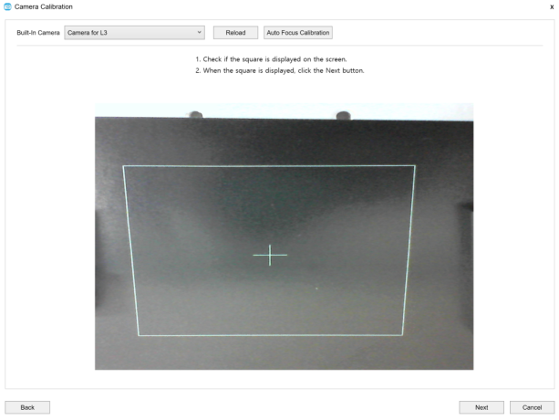
4. Check the camera window then click [Next].
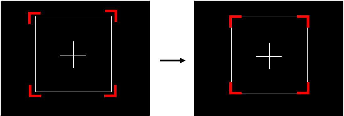
5. Align the four red borders to each corner of the marked rectangle.
Use your mouse to align the red borders and set their approximate position to the corners of the rectangle. Use the arrow keys on your keyboard to adjust and set the position of each red boarder. Once the red borders are aligned to the corners, click [Next].
 |
| [Camera screen] |
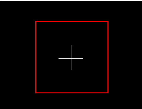
6. Check whether or not the red border matches the marked border on the camera screen. If the red border appears misaligned or unmatched, go back to step 5 and readjust its position.
 |
| [Camera screen] |
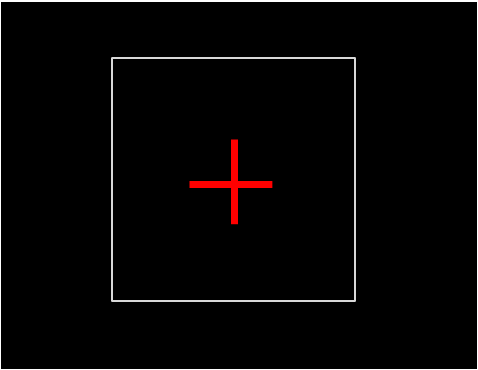
7. Check whether or not the red [+] cross mark matches the marked [+] cross on the camera screen. If the red cross mark appears misaligned or unmatched, use the arrow keys on your keyboard to adjust its position. Then, click [Next].
 |
| [Camera screen] |
¶ 12. Manual calibration
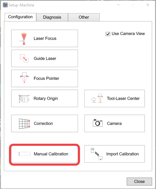
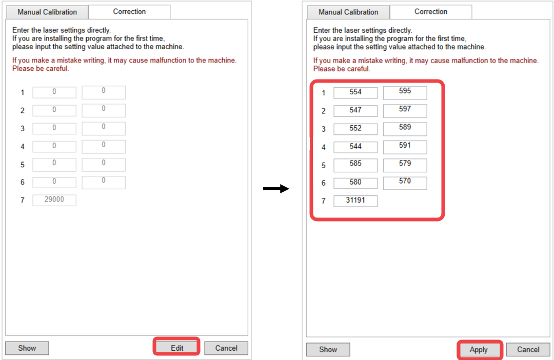
1. Click [Manual calibration].
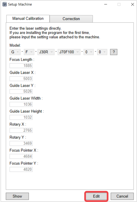
2. Click [Edit].
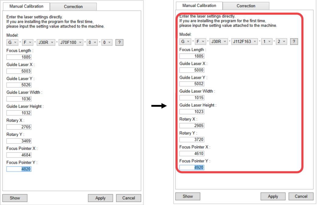
3. Enter the setting values then click [Apply].
4. Select [Correction]. Enter the setting values then click [Apply].
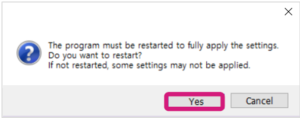
5. Click [Yes] to restart the program.
¶ 13. Import calibration
1. Click [Import Calibration].
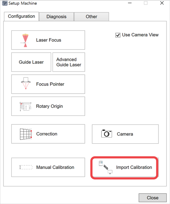
2. When the serial number is entered, the correction value stored in the server is automatically called and set.
✽Network connection is required to run this function.