※The machine is initially set up at the factory. Please contact your reseller first before making any changes to the settings of the machine.
※ Calibrate the machine in the following order: Laser focus calibration – Guide laser calibration – Focus pointer –Correction – Rotary origin calibration (if in use) – Camera.
※ A separate program for Setup Machine is provided. Run the program first to calibrate the machine.
※Use appropriate material for calibration. The machine’s warranty service does not cover mishandling of the machine resulting in damage or failure.
※ Use a black anodized aluminum material.
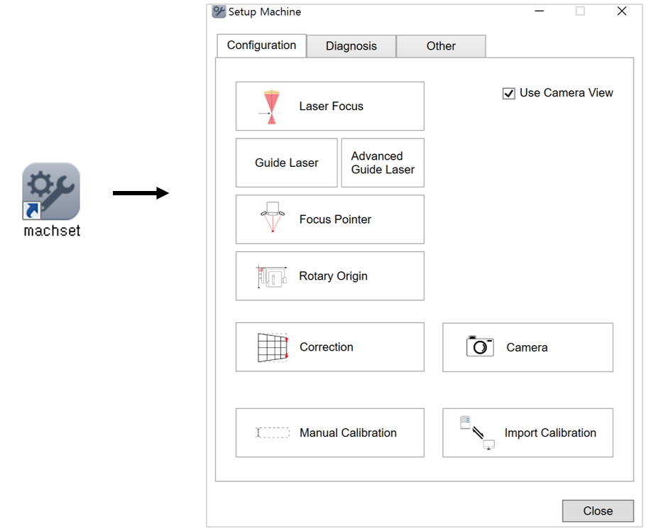
¶ 1. Use camera view
Select the checkbox (on the top right corner) to display Camera Viewer.
Use Camera Viewer to accurately check and calibrate each setting.
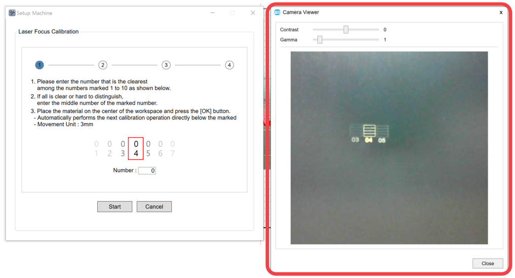
¶ 2. Laser focus calibration
Match the laser focus to the height of the material to increase accuracy when marking.
There are four stages involved when calibrating the laser focus.
On each stage, the head moves according to the distance specified in the previous stage and the movement interval shortens.
[How to calibrate laser focus]
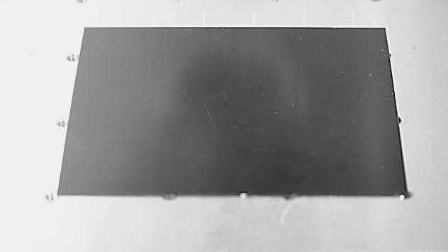
- Place the material on the work area.
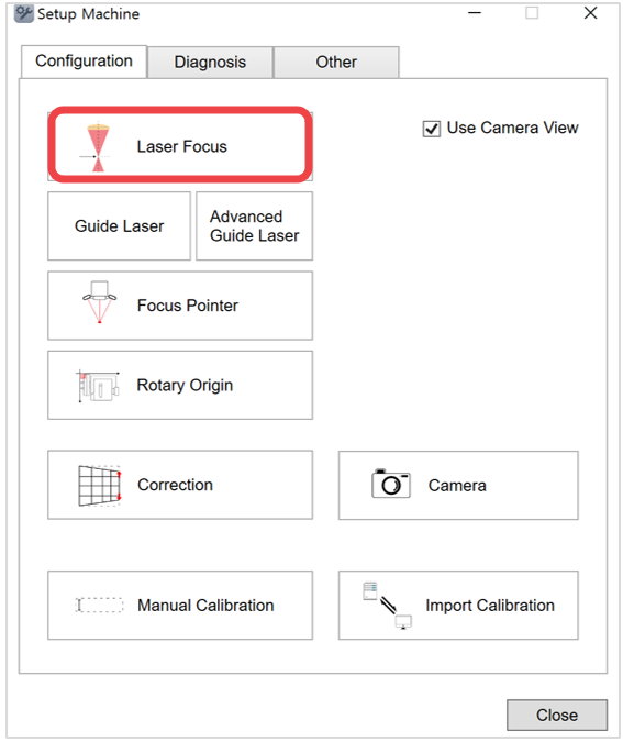
- Click [Laser Focus].
- Read the notification displayed on the screen then click [Next]. Read the instructions that will appear on the screen then enter the height of the material.
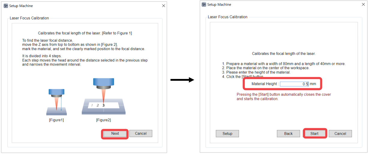
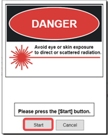
- Be sure to read the warning notice first before clicking [Start].
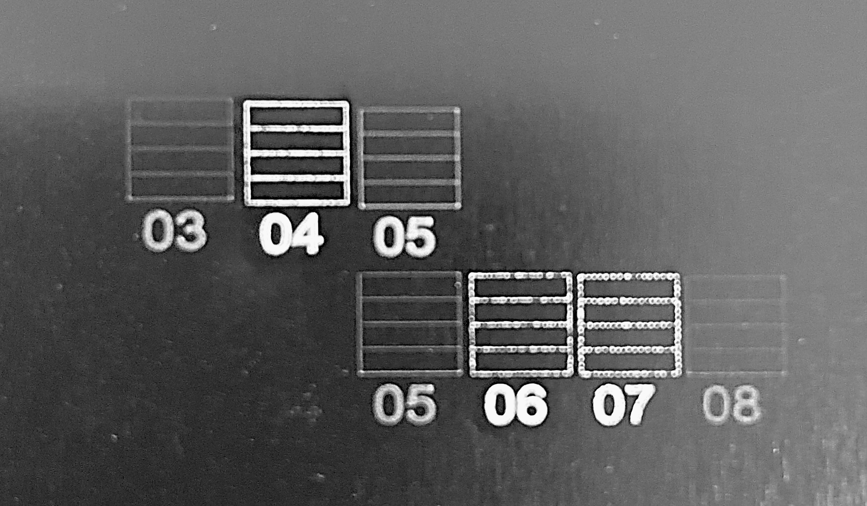
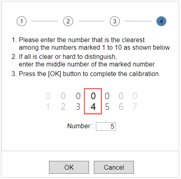
- The numbers and circles are engraved on the material with a laser.
Numbers 01~10 are engraved, and the numbers may vary depending on the laser focus.
- In [Setup Machine] window, enter the median number among the engraved numbers then click [OK].
For example, if the engraved numbers are 01, 02, 03, 04, 05, 06, 07, 08, 09, 10 enter the median number ‘05’ (or the number in the middle) then click [OK].
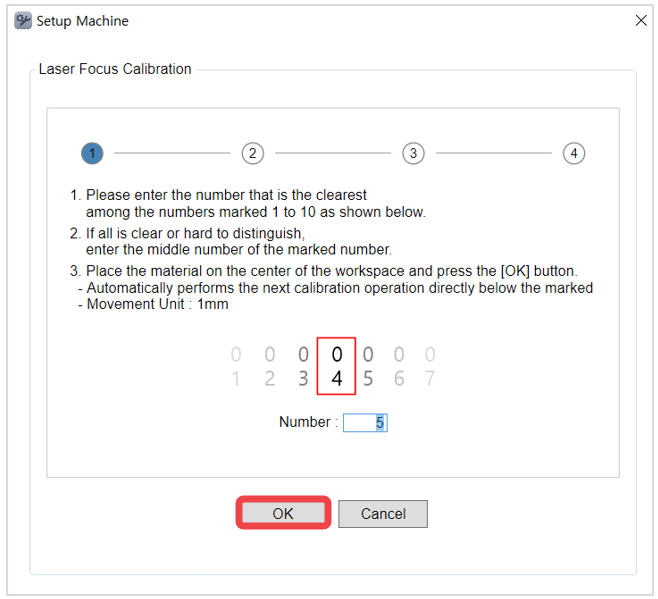
- Repeat [step 5] and [step 6] four times to complete laser focus calibration with optimized option.
¶ 3. Guide laser calibration
Calibrate the size and position of a guide laser.
[How to calibrate guide laser]
- Place the material on the work area.
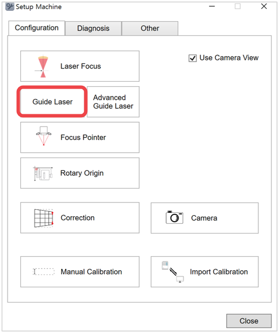
- Click [Guide Laser].
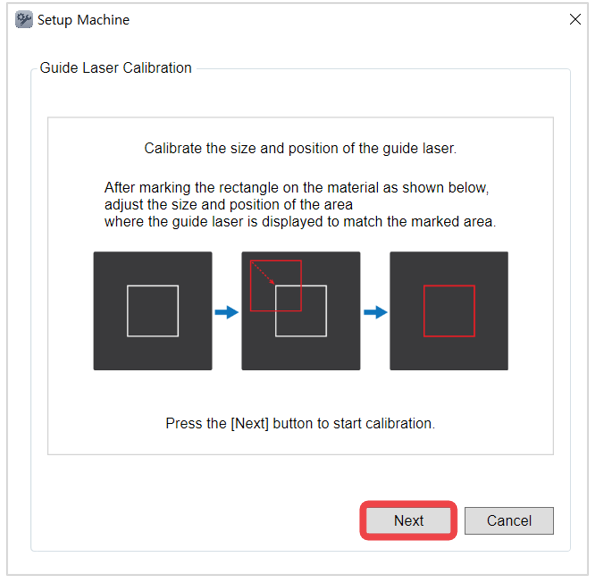
- Read the notification then click [Next].
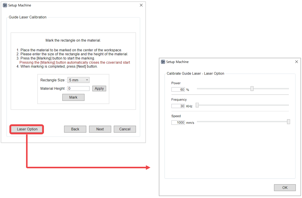
- Select the size of the rectangle then enter the height of the material (to mark a rectangle). Click [Apply] to set the height then click [Mark]. Once [Mark] button is clicked, the machine cover automatically closes and the rectangle is marked on the material.
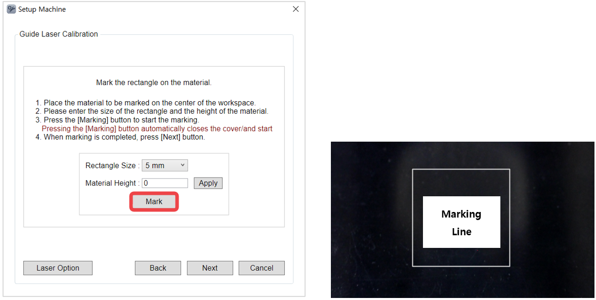
*A 20mm rectangle is marked on the material at a 0.5mm height.
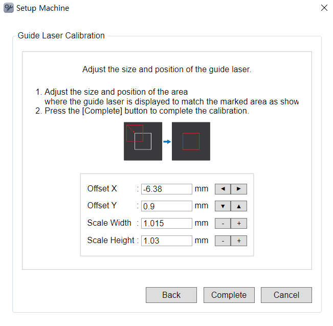
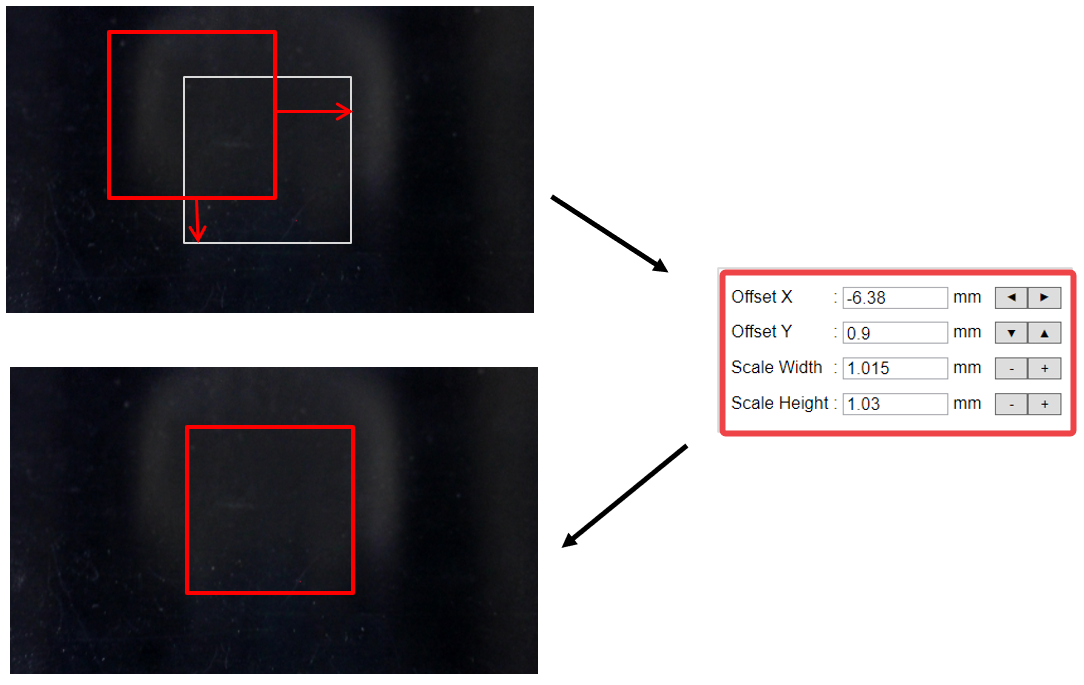
- Once the guide laser appears at the end of marking, adjust the offset values, width and height to fit in the rectangle in [2. Parameter Setting] then click [Apply].
※Select [Laser Option] in the [Guide Laser Calibration] window to adjust the laser options.
[Advanced Guide Laser]
- In [Setup Machine] window, click [Other].
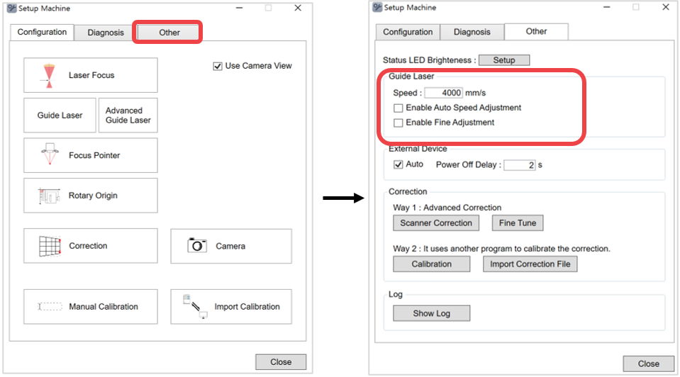
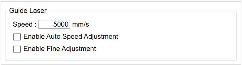
| Speed | Sets the guide laser speed |
| Enable Auto Speed Adjustment | Automatically adjusts the guide laser speed according to the size of the object to be marked when selected. |
| Enable Fine Adjustment | Automatically moves to the guide laser focus position (when checking the marking area) to enable precise marking area position when selected. ✽[Advanced Guide Laser] menu is added to the [Setup Machine] window when [Enable Fine Adjustment] function is selected and/or activated. ✽[Advanced Guide Laser] is required for calibration, and the calibration method similar to guide laser calibration method. 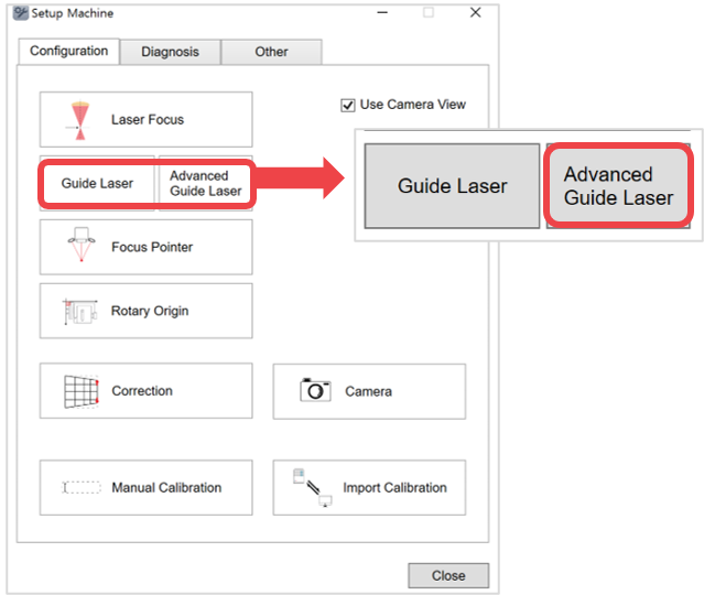 |
¶ 4. Focus pointer
Set the position of the head laser pointer and V laser pointer.
| L-wrench (2,3mm) |
 |
1EA | For setting the focus pointer |
- Select [Focus Pointer] in the Machine Settings.
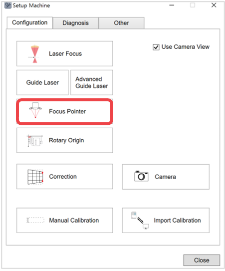
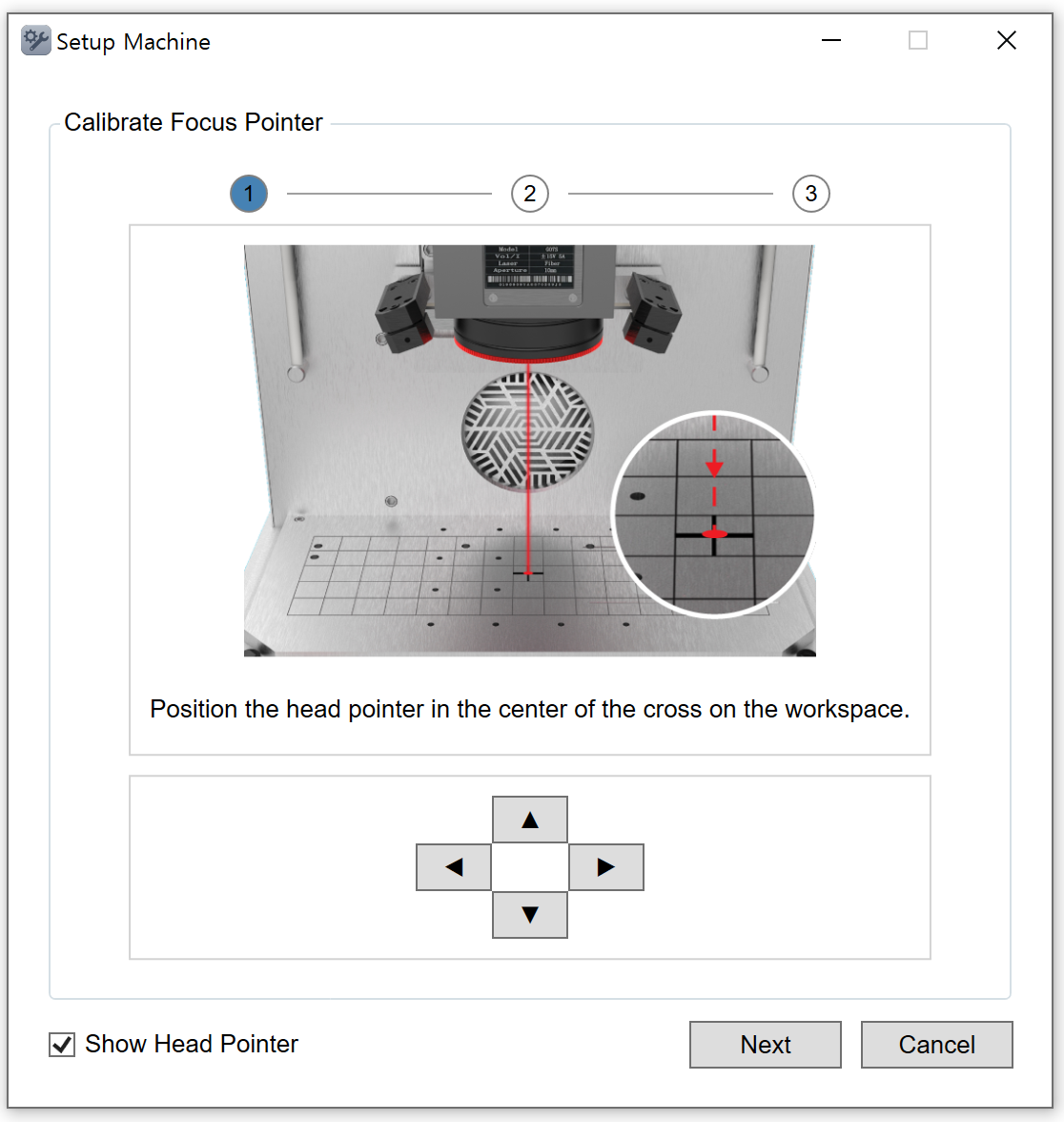
- Position the head laser to the center of the work area. Use the direction key buttons to position it to the center. Then, click [Next].
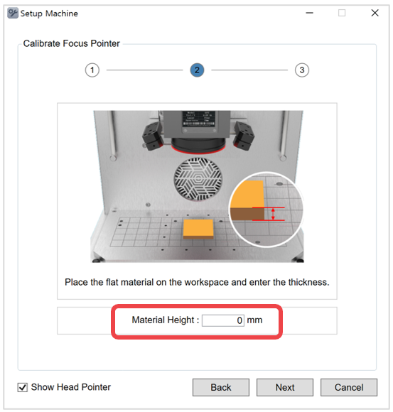
- Place the flat material on the work area and enter the thickness. Then, click [Next].
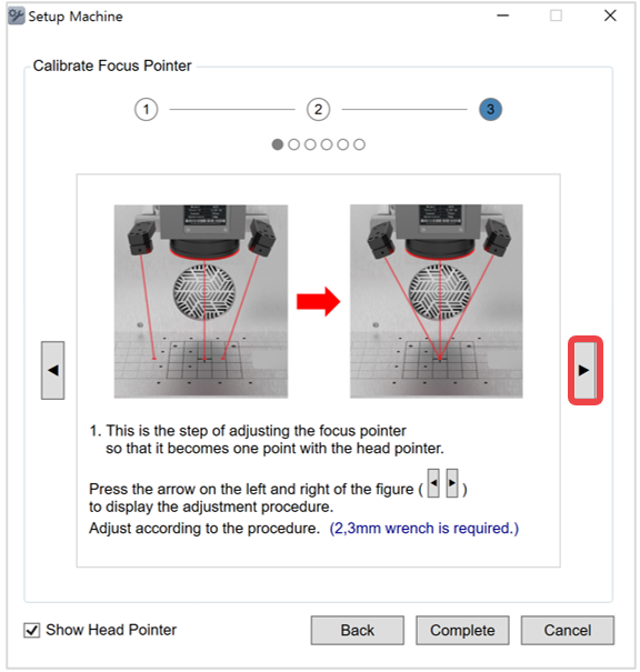
- P Click ▶ button on the right to proceed in sequential order. ※Use a 2,3mm wrench.
Take note that the setting process involves 4 steps. Be sure to proceed with both left and right pointers in the same process.
¶ 5. Rotary origin
Calibrate rotary origin if rotary clamp is in use.
¶ How to calibrate rotary clamp origin
- Place and secure the rotary clamp to the work area.
- Click [Rotary Origin].
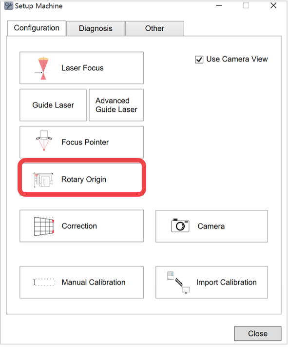
- If rotary clamp auto tilting function is enabled, first, set the tilting origin to 0 degree.
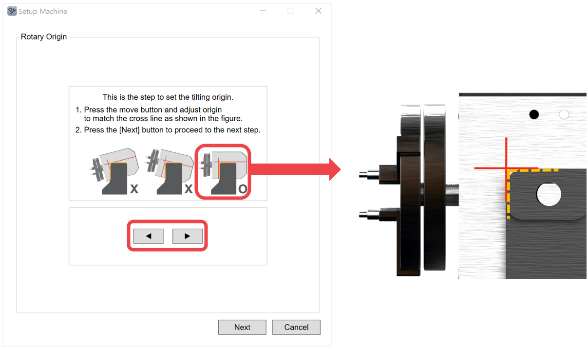
¶ How to set the tilting origin to 0
Match the clamp angle with the cross mark on the clamp body (as shown above).
Click  up/down button to adjust the angle by 0.1 degree.
Once the angle is positioned to 0 degree, click [Next].
| Setting tool | 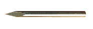 |
1EA | Tool for rotary origin setting. |
- Insert the setting tool into the rotary (as shown below).
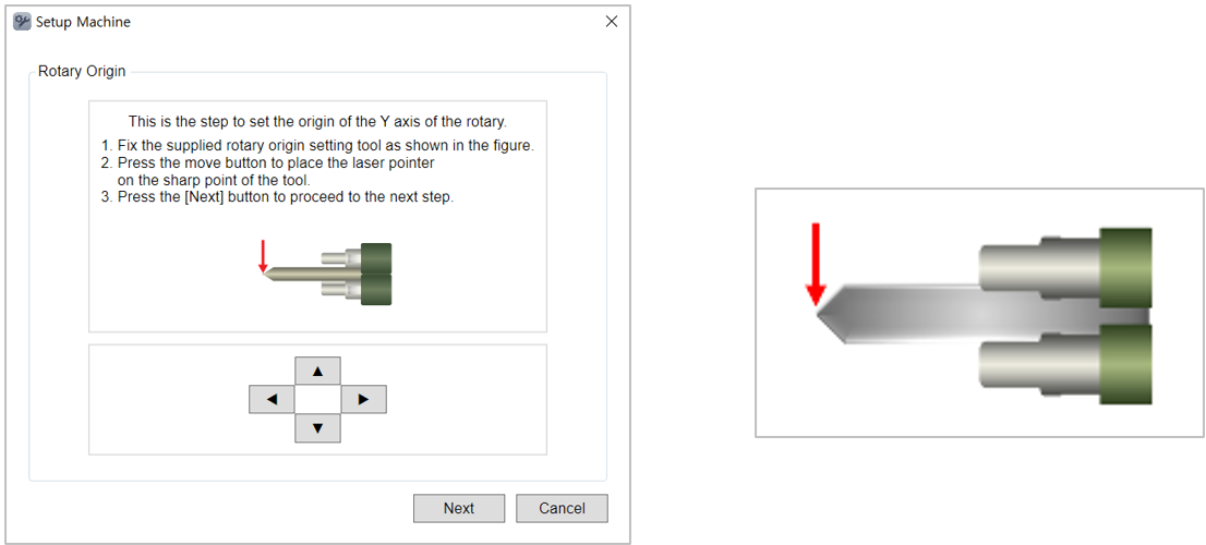
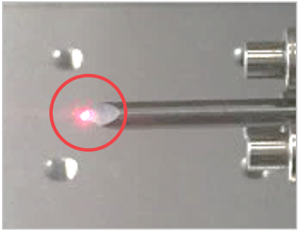
- Match the tip of the tool to the laser pointer. Use the direction key buttons to position the laser pointer to tip of the tool. Then, click [Next].
Or, on the machine, use
 buttons then long-press
  button (for more than 1 second).
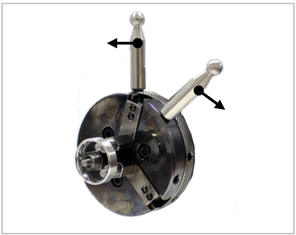
- Remove the setting tool then insert the ring into the finger chuck (as shown below). Use both finger chuck handle to tighten the clamp and secure the ring.
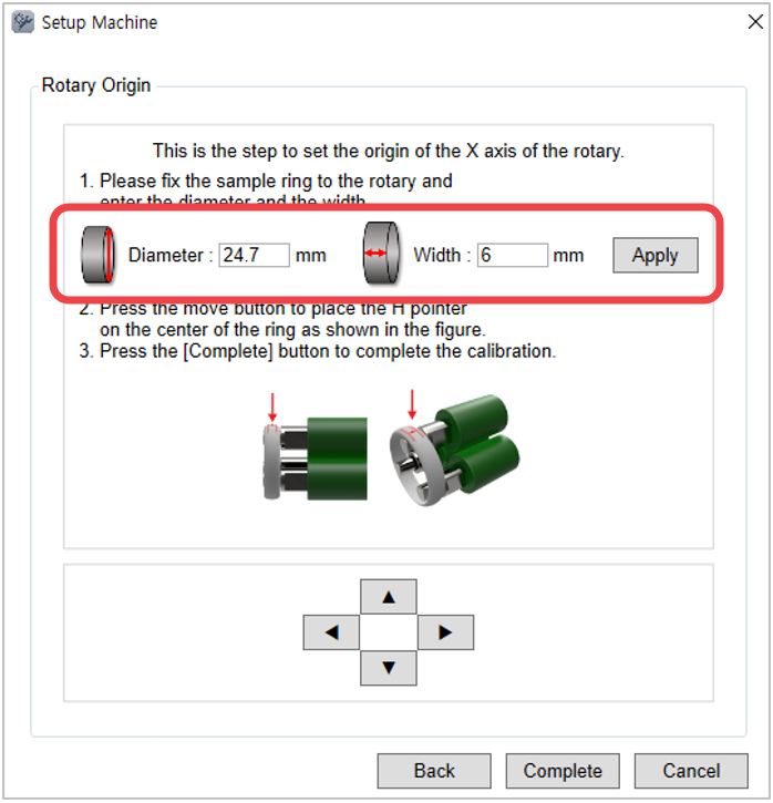
- Then, move to the next step. Enter the size of the ring.
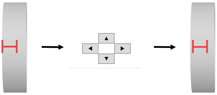
- Move the [H pointer] to the center of the ring by using the direction key buttons. Then, click [Complete].
¶ How to calibrate bangle clamp origin
- Place and secure the bangle clamp to the work area.
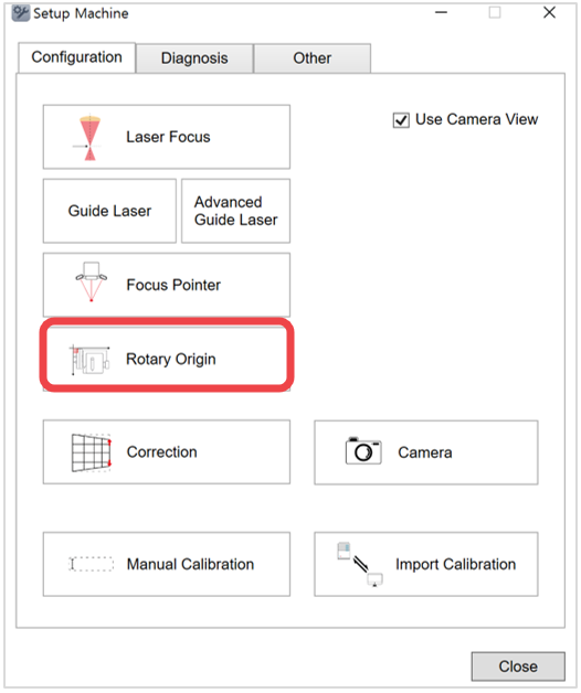
- Click [Rotary Origin].
- If bangle clamp auto tilting function is enabled, first, set the tilting origin to 0 degree.
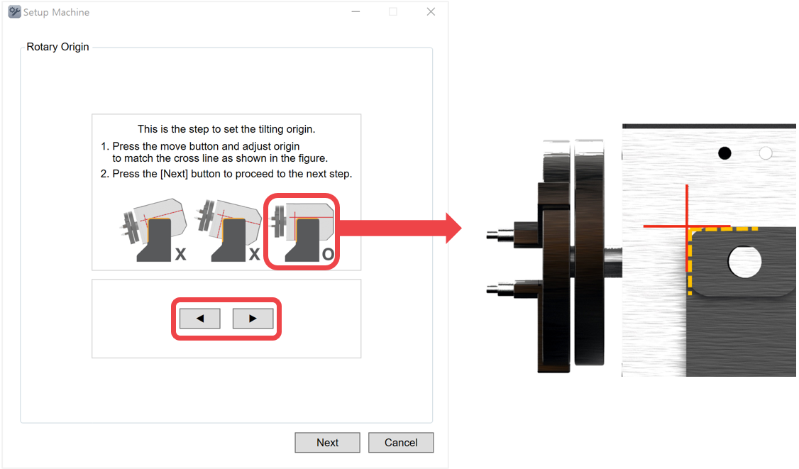
Match the clamp angle with the cross mark on the clamp body (as shown above).
Click up/down button to adjust the angle by 0.1 degree.
Once the angle is positioned to 0 degree, click [Next].
※Unlike the rotary clamp, adjusting the left-right position saves the setting permanently, even after restarting the program.
¶ 6. Correction
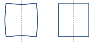
The father the laser moves away from the center, the greater the distortion occurs.
When the laser passes through the lens after passing through the scan head, the farther it moves, the more distorted the shapes become (see figure on the left).
To correct distortion, correction process is used (see figure on the right).
[How to calibrate correction]
- Use a material larger than (110x110 mm). Preferably, with a size of (120x120 mm).
- Click [Correction].
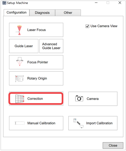
- Read the notification on calibration process. Click [Next] to start calibration.
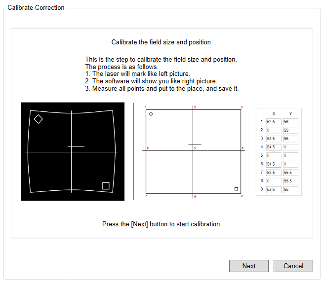
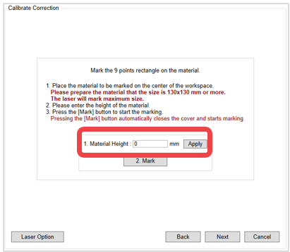
- Enter the height of the material then click [Apply]. Click [Mark] to start marking.
- Measure the coordinate values in each corner. Enter the sizes then click [Complete] to finish calibration.
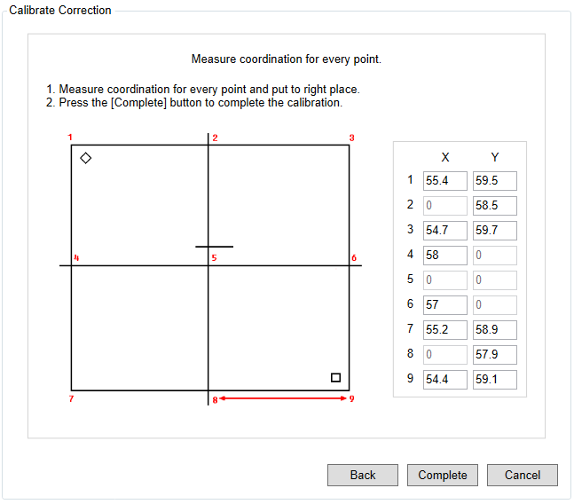
Be sure to measure the size from each corner (as shown below).
¶ 7. Camera
- Place the material on the work area. ※Use a black paper when setting the camera
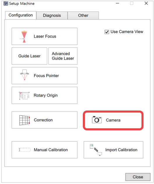
- Click [Camera].
- Enter the height of the material (to mark a rectangle) then click [Apply].
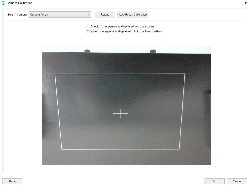
Once [Mark] button is clicked, the machine cover automatically closes and an (80*80mm) rectangle is marked on the material.
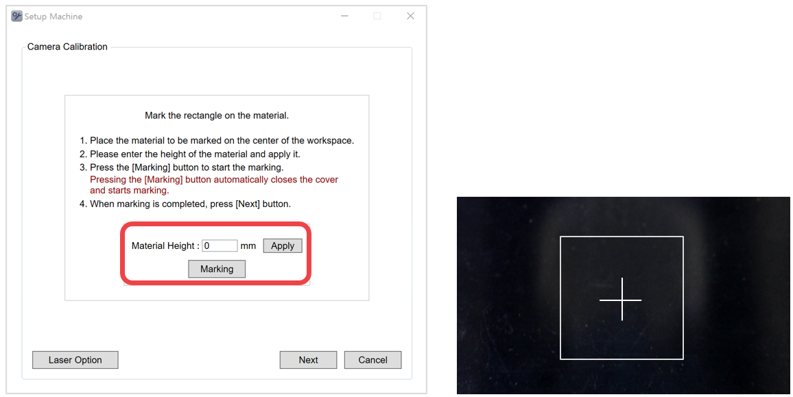
- Check the camera window then click [Next].
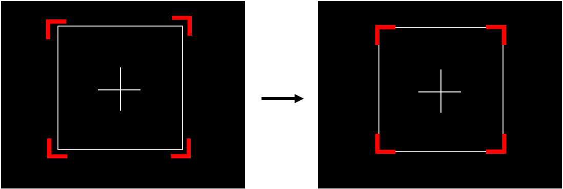
- Align the four red borders to each corner of the marked rectangle.
Use your mouse to align the red borders and set their approximate position to the corners of the rectangle.
Use the arrow keys on your keyboard to adjust and set the position of each red boarder.
Once the red borders are aligned to the corners, click [Next].
 |
| [Camera screen] |
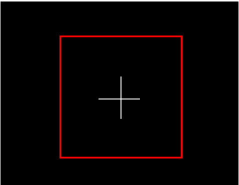
- Check whether or not the red border matches the marked border on the camera screen.
If the red border appears misaligned or unmatched, go back to step 5 and readjust its position.
 |
| [Camera screen] |
 |
| [Camera screen] |
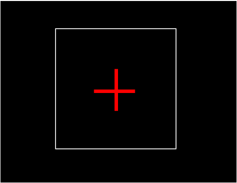
- The camera automatically recognizes the focus pointer and performs calibration.
Wait for the calibration to complete automatically.
Machine operation and program operation are prohibited during automatic calibration.
A completion confirmation appears once the calibration is completed.
¶ 8. Scan fine calibration
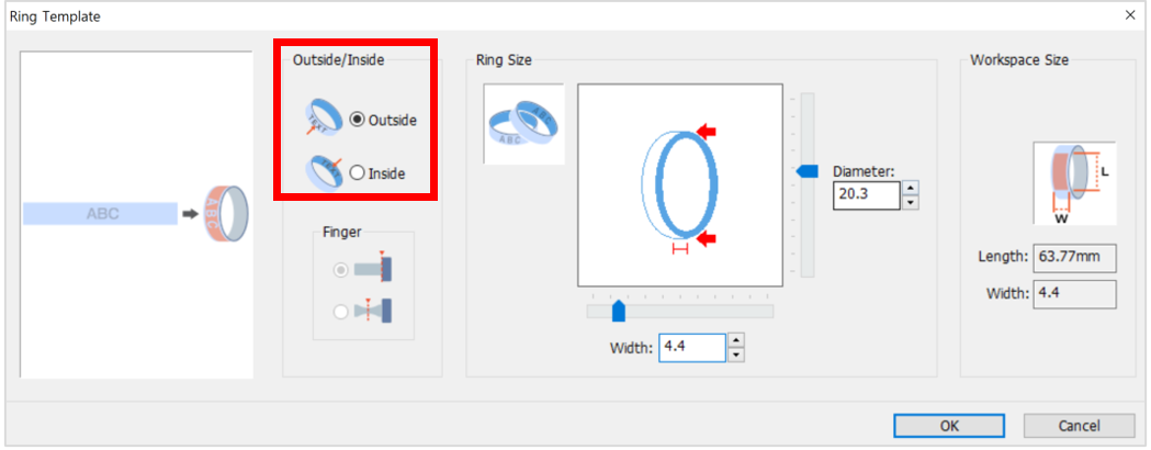
● Outer diameter and inner diameter scans must be calibrated separately. (Depending on the outer diameter or inner diameter option selected in the ring template.)
If the marking position is incorrect, it can be adjusted using Scan Fine Calibration.
-
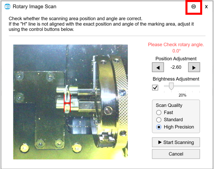
Select a ring template in the program, then choose either the inner diameter or outer diameter to calibrate. Secure the material in the rotary clamp, then select [Rotary Image Scan] in the [Camera] section of the program.
-
Select the [Settings] icon in the upper-right corner of the [Rotary Image Scan] window.
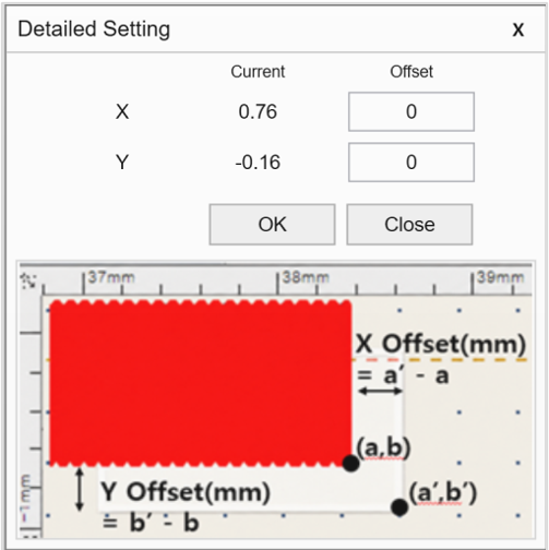
- Scan again without moving the material. Compare the scan result with the actual material position, then enter the X/Y offsets in the detailed settings window to correct the position.
• The current value field displays the detected position error. Enter the required correction value in the Offset field. The final value is calculated by adding or subtracting the offset from the current value.
For example, if the current value is 0.92 and -0.1 is entered in the Offset field, the final value becomes 0.82.
• X Offset: Corrects horizontal positional errors in the scan results.
• Y Offset: Corrects vertical positional errors in the scan results.
• The outer diameter offset configured during outer diameter scanning is automatically applied to the inner diameter offset during inner diameter scanning.
¶ 9. Manual calibration
- Click [Manual calibration].
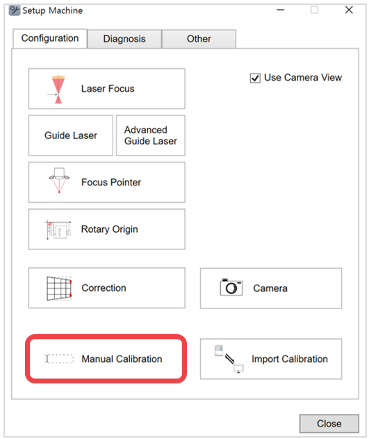
- Click [Edit].
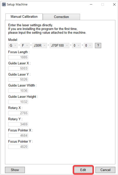
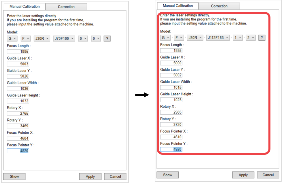
- Enter the setting values then click [Apply].
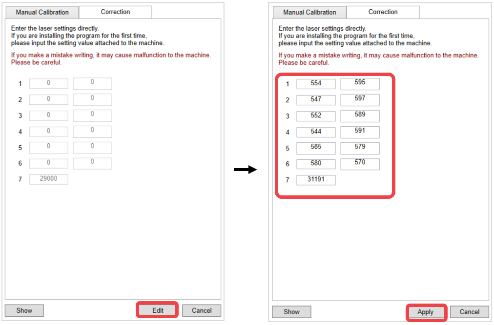
- Select [Correction]. Enter the setting values then click [Apply].
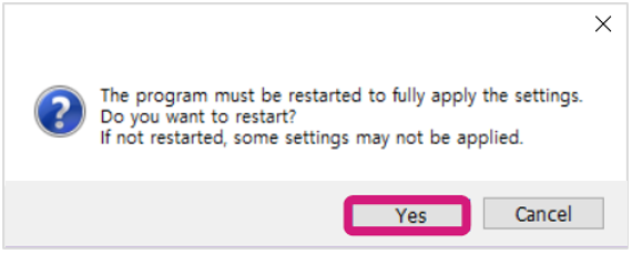
- Click [Yes] to restart the program.
¶ 10. Import calibration
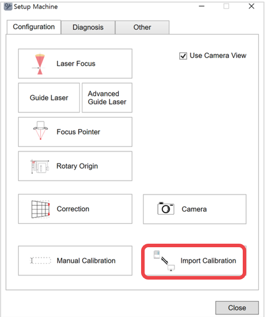
- Click [Import Calibration].
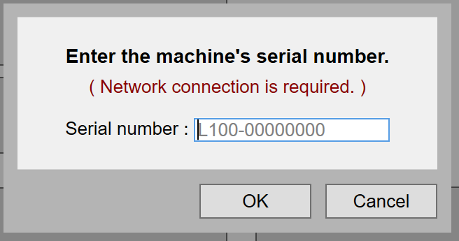
- When the serial number is entered, the correction value stored in the server is automatically called and set.
Network connection is required to run this function.
Go to the L3 Prime Maintenance➜